Apollo 13: Analysis of an Accident
by Aerospace Engineer Xavier Pascal

Apollo 13 turned out to be a very different mission due to an oxygen tank explosion. Therefore there was no TV coverage of the lunar module (LM) landing on the Moon, nor of it returning to the command and service module (CSM). There were no photos or TV coverage on the lunar surface either, with no photographic shadows, lighting or perspectives to analyse.
But this does not mean that there were no anomalies in this mission.
We will consider the Apollo 13 Mission Report.
The most interesting aspect of all the Apollo mission reports is usually towards the end where there are often many surprises. Later, we will examine two photographs taken during the mission that are incompatible with each other, and which contribute to the overwhelming evidence pointing to the fact that this mission was faked.

There was a successive chain of events leading up to the Apollo 13 oxygen tank explosion, with each event causing the next – the classic 'domino effect'.
The pressure increased in one of the tanks, then decreased because the relief valve was opened, and then increased again as the relief valve reseated. It was claimed that this action caused a vibrational disturbance on an accelerometer. But an accelerometer is a device which measures accelerations (or decelerations), and does not react to variations of pressure in a tank.
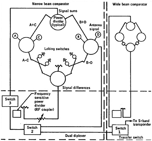
Apparently the panel separation from the craft damaged a dish on the CSM antenna and, as a result, the high-gain antenna switched from narrow beam to wide beam. But the wide beam mode required that all the dishes were operational, while the narrow beam could actually work with a dish not operating properly. Therefore it is the converse that should apply: it should have switched from wide beam to the narrow beam.
The Apollo 13 Mission Report lists the conditions which could have prevented the accident:
- The electrical wires should have been made of stainless steel instead of aluminium.
- The fill-line plumbing internal to the tank needed improvement.
- The astronauts should have been warned of an inadvertent closure of either the fuel cell hydrogen or oxygen valves.
- There were only two cryogenic tanks in the service module instead of three.
- In the fuel cell oxygen supply valve, the polyetrafluoroethylene coated wires should have been isolated from oxygen.
- There were not enough immediate and visible warnings of possible anomalies in all systems.
In the case of such an important mission, surely all these points should have been addressed, fixed and checked well before the mission.
There was an anomaly in the post-landing vent valve – this post landing ventilation inlet valve was found to be closed (rather than open) after the landing by the recovery personnel. This malfunction was due to the handle of the ventilation valve not being pulled open fully. As a consequence of this, the valve would have remained closed instead of open. The Apollo Operations Handbook states that this handle should be pulled open to its full extent.
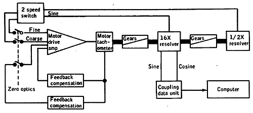
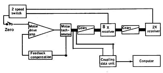
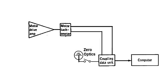
The report discusses shaft fluctuations in the zero optics mode, and presents the above schematic for the “Zero Optics Mode Circuitry”. In fact this schematic is totally incoherent for the reasons given below.
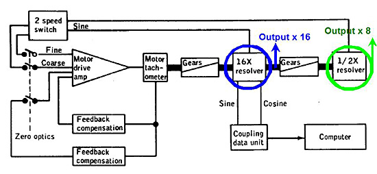
Firstly, we find that the output of the tachometer was initially multiplied by 16 (in frequency), and then divided by 2, giving a tachometer signal multiplied by 8. This illustration is illogical.
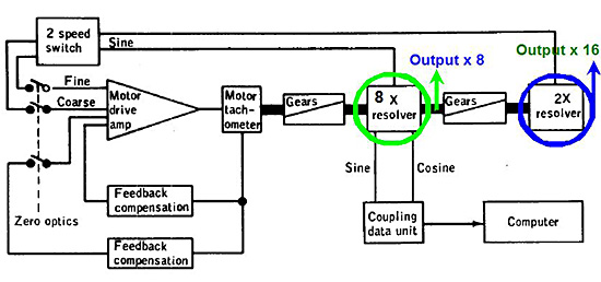
It would be far simpler to first multiply the tachometer signal by 8, and then multiply it by 2 in order to obtain a tachometer signal multiplied by 16. The same two signals would be obtained (in reverse order) but in a much simpler way – using fewer electronics.
Then we see that a sine transformation was applied to one of the multiplied signals (but not the other). However, it makes no sense to apply a sine transformation to a pulsed signal. The two multiplied signals are then inputted into a two-speed switch block which must output a single signal. Instead, this switch block outputs two signals, both of which come into the motor drive amp.
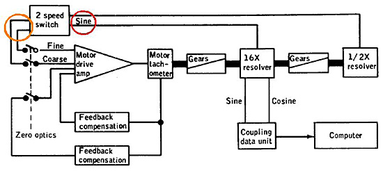
The confirmation of this incoherence is that in the same interface used in Apollo 12, this block outputs a single signal, as seen above. (Then again, the Apollo 12 one is incoherent too, but in a different way.)
Then there is permanent feedback compensation, but there is also another one which is applied in case the zero optics switch is closed; the second one is totally superfluous, as there is one there already.
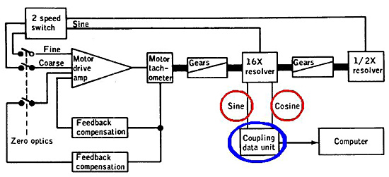
After which there are two signals inputted into the CDU from the 16x resolver. The CDU (Coupling Data Unit) is a device which transforms data signals into an usable form for the computer; here it consists of counting the tachometer pulses, and feeding the corresponding count to the computer.
There are two input signals, for the phase difference between these two signals to know which direction the motor is turning, and whether the pulses should be counted or discounted.
The abnormality is that:
1) The sine and cosine functions are applied to the pulsed signals – this makes no sense whatsoever.
2) The inputs should come directly from the tachometer output, and not the multiplied signal.
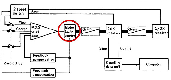
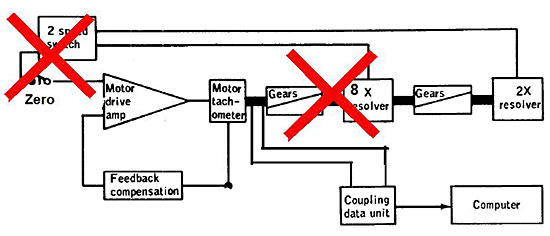
The motor drive amp output feeds into a motor tachometer (circled in red).
What is a tachometer?
A tachometer is a device that generates pulses from the rotation of a wheel. Its resolution is characterised by the number of pulses generated per full rotation of the wheel.
- It measures the rotation of the wheel by counting the number of generated pulses.
- It also allows the speed of a spinning wheel to be measured – the faster the frequency of the generated pulses, and the faster the rotation of the wheel.
- It is used to measure the speed of automobiles, since the rotation speed of the wheels is related with the speed of the vehicle.
A tachometer also permits following the displacement of a conveyor – indicating how much a conveyor has moved, the number of generated pulses read is multiplied by the circumference of the tachometer wheel, and then divided by the number of pulses per full rotation of the wheel, thereby obtaining the distance the conveyor has travelled.
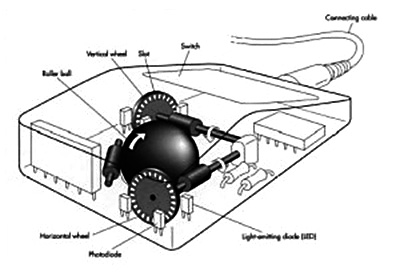
This principle is also used in a mechanical computer mouse. As the mouse is moved, a spherical ball turns which makes two perpendicularly placed wheels turn, each of which send pulses to an electronic circuitry. They are then are counted or discounted to update the position into which the mouse moves.

This is how a computer knows where the mouse is positioned, and as the mouse moves, it updates the position of the cursor on the screen.
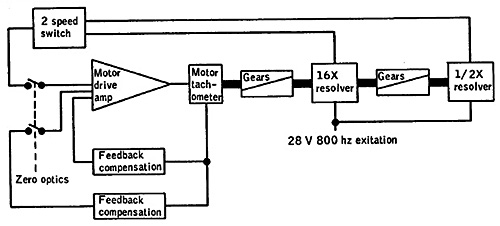
If the interface is corrected to eliminate all the anomalies discussed, we obtain the following:
- The signal is first multiplied by 8, and then by 2, to obtain the two multiplied signals.
- The multiplied signals are input into the speed switch block, without applying a sine transform to one of the signals, and only one output comes out of this block.
- The redundant feedback compensation is suppressed.
- The outputs of the tachometer directly enter the CDU, without sine and output transforms being applied to them.
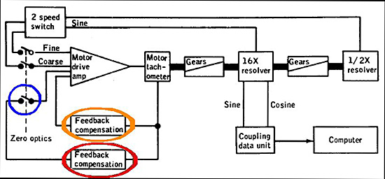
However, if this new interface is more logical than the original one, it still does not mean that it is correct.
Firstly, the zero optics cannot be obtained just by looping the multiplied signals on the motor drive amp.
What does obtaining zero in the optical system mean?
It means that when the optical system is centered, the system has to be warned that it must take it as a reference, and count or discount pulses from this reference. It certainly cannot be achieved just by looping the multiplied tachometer signals.
So the multiplied blocks of the tachometer signal are totally useless, and their output signals should not be looped back on the motor drive amp.
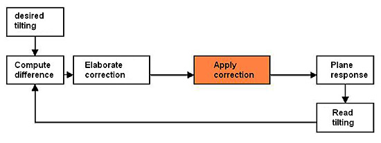
What is feedback compensation, and when is it used?
The feedback compensation is used when the command needs to produce a desired effect, and the produced effect can be measured; the desired effect and the measured effect are then differentiated and the result is used to correct the command until the measured effect matches the desired effect.
So finally, after having eliminated the redundant and useless elements which should not be there, we obtain this final interface:
- The tachometer generates pulses on two signals, the phase difference of which allows us to know in which direction the motor wheel is turning (and know if the pulses need to be counted or discounted). These two signals are inputted into the CDU which counts (or discounts them); the computer can then read the count via an I/O instruction.
- A zero switch (or push button) is connected to the CDU; when this switch is set, it sends a signal to the CDU which allows it to clear the pulse counter of the CDU, with the result that when the computer reads zero on the counter, it knows the optical system is currently centered.
Now we have a coherent optical interface.
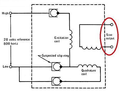
The Apollo 13 Mission Report includes the schematic of a "one-half speed resolver". But the problem with the above schematic is that if there is an output (circled with red), there is no input at all. An electronic interface designed to transform a signal always has at least one input and one output.
This schematic has just one output, but no input. Moreover, although this output is labelled "Sine output", it has absolutely nothing to do with a sine transform; it is not that simple to obtain a sine transform.
Moving on through the report, the High-Gain antenna acquisition problem is discussed. The CSM pilot adjusted the antenna angles with values which were given to him seven hours previously by ground control. But it so happened that these values were not currently the most favourable settings.
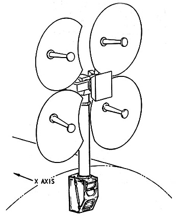
A little explanation is necessary concerning the CSM antenna:
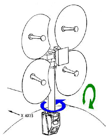
The CSM antenna could be rotated around two axes, a vertical axis, and a horizontal axis. The rotation around the vertical axis is the "yaw", and the rotation around the horizontal axis is called the "pitch".
Animated yaw rotation.
Animated pitch rotation.
The CSM antenna had to be oriented towards Earth to facilitate communication with Earth. There is only one combination of the yaw and pitch angles which would allow correct communication. If either the yaw or the pitch angle diverges too much from the correct orientation toward Earth, communication with Earth is impossible.
The antenna was oriented relative to the CSM which means that if the attitude of the CSM changed, the attitude of the antenna relative to the CSM had also to be changed so that the antenna remained correctly directed toward the Earth, allowing the communication to be maintained.
When ground control gave the CSM pilot values for the yaw and the pitch of the antenna, they were relative to the attitude of the CSM at that time. Seven hours later, the attitude of the craft had changed, so the values initially given by ground control were no longer applicable, and the pilot would have required updated values instead of using obsolete and useless pointing data.
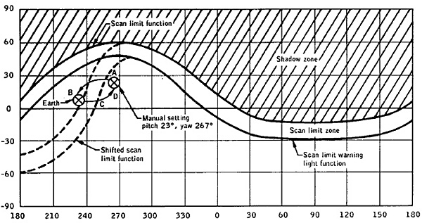
On the above graph, the horizontal coordinate represents the yaw angle, and the vertical one is the pitch angle. The white zone represents combined values of the yaw and pitch angles, while the hatched zone represents combined values of these angles for which communication with Earth was possible.
But this graph is totally absurd as it implies that there were plenty of combinations of the yaw and pitch angles for which the communication with the Earth were possible, whereas in fact there was only one combination permitting such communication. There is a curb representing the separation between the two zones, and another one which is parallel to the latter, which is the limit at which the scan limit warning lamp would become illuminated. This is all complete fantasy.
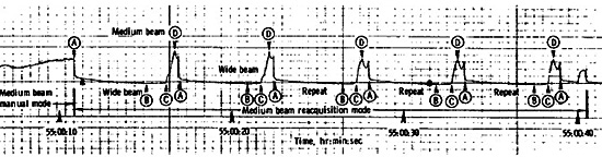
This graph shows the recorded signal strength, with peaks of five-second intervals. Over such a short period of time, the attitude of the CSM did not significantly change, which means that the attitude of the antenna did not need to be updated to maintain reception of a good signal. It means that the quality of the signal over this short period of time should have remained constant, and not show the sudden peaks.
 |
There is discussion of a malfunction on a "entry monitor system 0.05g light". One may ask why would there be a warning on an acceleration (or deceleration) of 0.05 g, which is not an abnormal condition.
In the event that this lamp would not go on, the crew were supposed to start the system manually by switching to the backup position. But how could the astronauts know there was a 0.05g condition, since the only visible way for them to be warned about this condition precisely was this lamp?
There was no signal on the AGC indicating this condition. Then, apparently when this condition occurred, the scroll began to drive, and the range-to-go counter began to count down; but what was the relationship between the 0.05g condition and these actions?
The report states that there was a gas leak in "Apex Cover Jettison System". The improvements are listed that could have avoided the problem:
- Improvement of assembly procedures.
- Addition of a thermal barrier of polyimide sheet to the interior of the breech plenum area.
Of course, these improvements could and should have been completed before the mission.
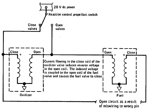
The report addresses the failure of a reaction control isolation valve. Stating that during the post flight examination, a fuel isolation valve was found open instead of closed. The investigation revealed that incredibly, the lead from the fuel valve closing coil was wired to an unused pin on a terminal board instead of to the correct pin.
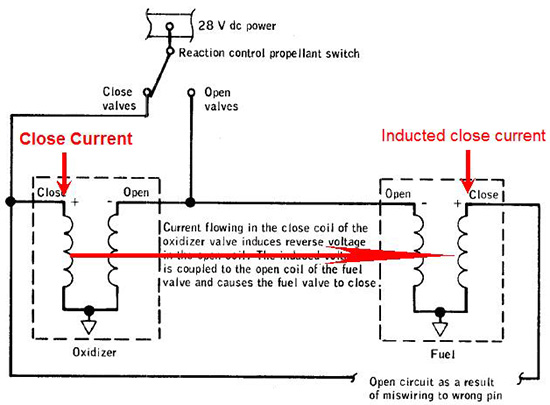
Apparently during the tests nothing was observed because the bus voltage would have been high enough for the oxidizer closing coil to act by induction on the fuel closing coil – also closing the fuel valve. But during the mission the bus voltage would have been a little lower, and this induction would then not have worked.
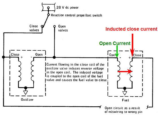
The above explanation is patently ridiculous, because if it could operate that simply when a current was sent into the fuel opening coil, there is no reason why it would not also act by induction on the closing coil, since it is closer to the fuel closing coil than to the oxidizer closing coil.
It is obvious that these coils should have been isolated from each other so they could not act by induction one upon the other. So this explanation is very obviously whistle-blowing by the engineers responsible.
 |
The mission report states that abnormal indications of the water tank level were observed. But the report says that it was not necessary to worry about these abnormal indications, for there was another way to know the level of the water in the tank.
Indeed, the tank was automatically refilled with fuel cell water, and the fuel cell water generation rates could be computed from power generation levels. The only problem is that when the water tank was full, the fuel cell did not stop producing water, but the water it produced was diverted to the waste water tank which was periodically dumped overboard
Therefore, without knowing the quantity of water which had been diverted to the waste water tank, the information regarding the total quantity of water produced by the fuel cell was useless (and the astronauts emptied the water tank faster than the fuel cell refilled it).
This is an obvious misrepresentation, because if things had been done properly, the fuel cell would have stopped producing water when the water tank was full, instead of diverting it to the waste water tank.
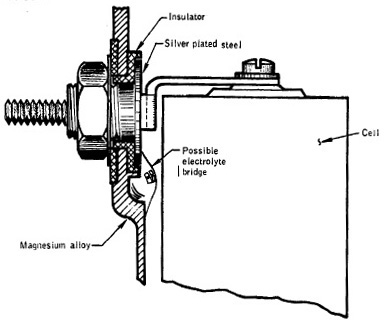 |
There were also problems with a lunar module (LM) battery, these came from an electrolyte leak.
So, for the subsequent lunar missions, the space agency made the following improvements:
- Coating the inside of the battery case with epoxy paint before the battery was assembled.
- Changing the potting material used at the ends of the case to a material which had better adhesion characteristics.
- The cell chimneys would be manifolded together and to the case vent-valve with plastic tubing.
It seems that the batteries used in automobiles at the time were safer than those used in the LM.
A battery malfunction light would have illuminated at about 100 hours of usage, with a corresponding master alarm.
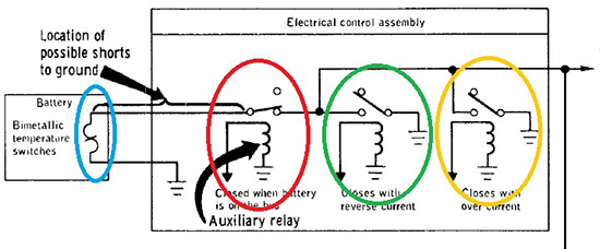
This malfunction could be caused by an over current or reverse-current condition. It is not important that this problem occurred, but it is of interest that this was the schematic for the battery malfunction circuit. There are three different default signals for the battery:
-
A switch which connects the default signal to the ground when there is a temperature excess in the battery, circled blue;
-
A switch which connects the default signal to the ground when there is a condition of reverse current, circled green;
-
A switch which connects the default signal to the ground when there is a condition of over current, circled orange.
The default signal is connected to the master alarm when the connection of the battery closes the switch, circled red.
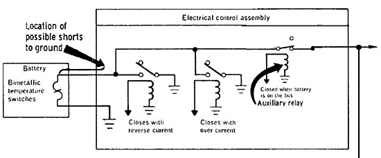
The problem is that the switch that connects the default signal to the master alarm should be located last, as on this modified circuit (above), and not between the default switches. There cannot be a condition of reverse current or over current for the battery when the battery is not connected.
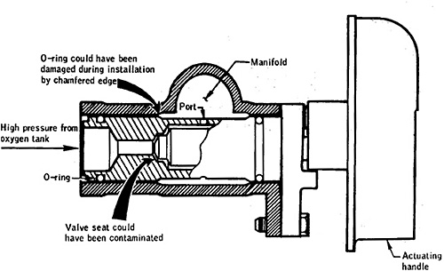
The pressure in the oxygen tank of the ascent stage of the LM would increase during the mission, indicating a reverse leakage through the shutoff valve from the oxygen manifold into the tank. Tests made prior the flight would have been inadequate, for they could only detect reverse leakage at high pressure.
The engineers changed the tests to be able to detect forward and reverse leakage at both high and low pressures. The LM was apparently sent on a very dangerous mission, with the eyes of the world upon it, without prior adequate testing.
It's all in the timing
 |
These astronauts had an onboard interval timer, with two timing ranges, used for routine functions like fuel cell purges.
But even here, there was a problem with this important timer, as unbelievably the time-period setting knob came off in an astronaut's hand due to a loosely fitted screw. This fault was found to be caused by an adhesive compound that did not provide sufficient retention for this application.
To solve this problem in the next missions the engineers secured the knob to the shaft with a roll pin. Even inexpensive timers operated more reliably than the timer apparently installed in the CSM.
Finally, in the case of Apollo 13 there were of course no lunar surface images, only photographs taken during the alleged journey to the Moon.

The Earth series was taken some 22 minutes apart. But even so, there is sufficient evidence to demonstrate that this was a fake situation. Here are two photos of Earth, AS13-60-8597 on the left, and AS13-60-8599 on the right, separated by 43 mins 58 secs.
What is abnormal about these two photos?
Independently, nothing, but, in conjunction with each other, they prove the hoax.
The Earth's terminator (shadow line) tilts over a long period as the inclination of the Earth's spin axis relative to the solar plane changes along its orbit around the Sun. But here, the interval between these two photos is relatively short, and therefore the terminator cannot tilt to such an extent relative to the Earth. In this case, the fact that it does change, strongly indicates that these images cannot have been taken during Apollo 13’s alleged journey to the Moon.
The change to the Earth's terminator is not a consequence of the rotation of the camera due to any change of attitude of the CSM. If the illuminated part was a single colour, say uniformly blue, then its orientation could not be established. But we can see artifacts on the illuminated part, and these artifacts maintain the same position relative to each other, so from these artifacts we can make an estimation of the orientation of the Earth.
Furthermore, the orientation of the shadow across the Earth was not compared with the horizontal, which would be dependent of the camera's orientation, but with a line passing the two recognisable artifacts on the illuminated side, that is not dependent on the camera's orientation. Any rotation of the camera between these two images, due to the CSM's rotation, is therefore irrelevant.
Conclusion
The Apollo onboard computer was so slow it was not in any way capable of controlling the severe pirouette that the craft would have incurred following the oxygen tank explosion. In addition, for the reasons given above, the antenna could hardly re-align again with Earth in a timely manner.
Everything concerning the errors in the fundamental design of the systems and failings discussed here contribute to the overwhelming evidence pointing to the fact that the Apollo 13 mission was faked.
Xavier Pascal
Aulis Online, updated February 2016
About the Author
Xavier Pascal is also a computer engineer specialising in real-time systems. He constructed a number of electronic interfaces with digital electronics in the 1970s and 1980s. Pascal states that he is sufficiently qualified to read and to fully understand the technical documentation of the Apollo Mission Reports, and his observations of the flaws in the documents (whether intentional or otherwise) form the basis of this article. Also see Xavier Pascal's article on the Apollo Guidance Computer Pascal 2012/3.
![]()
This article is licensed under
a Creative Commons License
AULIS Online – Different Thinking