Was the Apollo Computer flawed?
Note: the images in this article are not optimised for cell phones
An updated report on the AGC is available here
An investigation into the Apollo Guidence Computer documentation
The Apollo Guidance Computer (AGC) was a digital computer installed onboard each Command Module (CM) and Lunar Module (LM) providing interfaces for control of the craft. Most of the software on the AGC was stored in the Core Rope Memory. The AGC had a DSKY unit – a display unit with key pad.

This article will demonstrate that according to the published documentation the AGC was unfit for purpose.
Some say that it was not important if the Apollo Guidance Computer was underpowered because it was the mainframe computers back on Earth that were calculating the trajectory of the Command and Service Module (CSM). It is totally impossible for these computers to calculate in advance the entirety of the trajectory commands of the engines, because commands to an engine are only approximate and there is always a slight margin of error – over time such errors accumulate and become significant.
The only way to guide these craft was to have continuous control, constantly acquire instrument readings, compare them with the desired values and compute a correction to the engines. In this way a craft can accurately follow the desired trajectory. However, if the mainframe computers were doing the guidance, the readings would first have to be transmitted to them, taking at the very minimum 1.25 seconds. And after the commands have been calculated by the mainframe computers they would have to be transmitted back to the craft, which would take a further 1.25 seconds minimum.
So, if the mainframe computers on Earth were providing the guidance, there would be an accumulated delay of at least 2.5 seconds transmission time, which means that EVEN IF THEY WERE ABLE TO MAKE VERY RAPID CALCULATIONS OF THE GUIDANCE the mainframe computers could only react with a minimum delay of 2.5 seconds.
The period of guidance on the CSM/LM computer was of 2 seconds, which is less than the accumulated time of transmission for the guidance with the mainframe computers; this means that the guidance made by the ‘local’ computer was faster, even though considerably slower than the mainframe computers. In addition there was the possibility of a temporary loss of transmission during which the mainframe computers could not ensure guidance of the craft. So one must conclude that using the mainframe computers on Earth for guidance was both slower and unsafe.
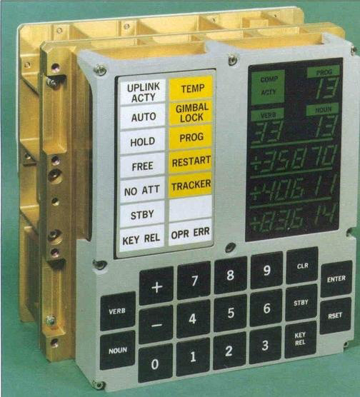
The Apollo Guidance Computer
It was generally accepted that the AGC was a brilliant computer, well in advance on its time, fully capable of guiding the Apollo craft to the Moon and back, as well as enabling the LM land on the lunar surface

The read only memory – the Core Rope Memory
The Core Rope memory of the CSM/LM computer was not actually functional (and could only be considered a joke) for several reasons.
Firstly, the connectors should have been able to convey more than 320 connections (the 64 sense lines, and the 256 signals to command the 256 cores of the card) and they were obviously not able to do so (some of the bare connectors are visible). Moreover, the sense lines are looped on the right.

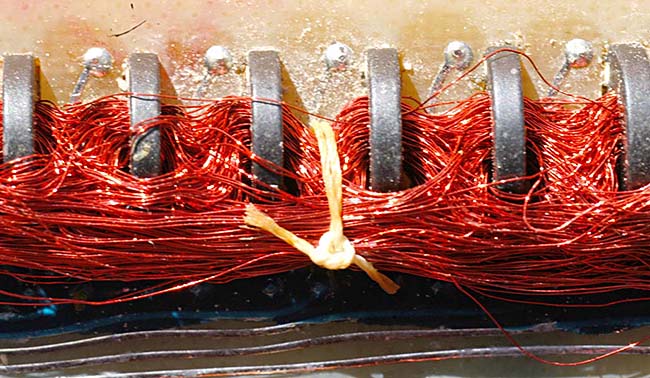
The Core Rope in close up
Up to 64 sense lines could go through a core, but it is physically impossible that all these sense lines would sense a current. Some of them are completely surrounded by other wires, and could not sense anything. This fact alone is enough to prevent the rope core memory from working.
But it doesn't stop there.
Activated Core Demo
Instead of individually activating the cores, the command lines were used as inhibit lines, as only one core could be activated at a time (otherwise when a sense line received an impulse, it would not be possible to know which of the activated cores generated the impulse) this means that each time the sense lines were 'read', there were as many cores as the number of cores of the memory card, minus one which must be inhibited (since only one must be activated).
The consequence of this concept is that a significant amount of energy would have had to be used (more than 200 amperes at each reading) and the card would seriously drain power from the batteries.

This schematic shows how the impulse generated by the cores was read. There were commands to activate the reading of the impulses generated by the cores individually. In order to select the sense line which generated an impulse into the output coil (circled in blue), line selection and module selection commands were used.
For example in the above schematic, the only sense line of the four which can generate an impulse into the coil is the one in light green, because it's the only one connected to both a selected line (represented in dark green) and a selected module (also represented in dark green). The three others, in light red, cannot generate an impulse into the coil as they are connected to either a) a non-selected line (in dark red), or b) to a non-selected module (also in dark red) – or even to both.
The problem with this selection circuit is not that it does not work, but that it reduces the current of the sense impulse; it divides it by three.

The Amplifier Sense Circuit
The 'read' impulse was then amplified – even if the impulse had been correctly acquired from the sense lines – it would have been incorrectly amplified by the amplifier sense circuit as described (see diagram above). This amplifier was a push-pull which only half worked (due to a missing connection) and due to an output transistor which was incorrectly mounted.
Univac Core Rope Memory
I became aware of this core rope memory used in an Univac computer. However, unlike the Apollo computer, the core rope memory of Univac was not used to make it run, but only to allow it to start. This core rope memory had 'only' 512 words of memory, far from the impressive memory of the computer of Apollo. In both of these core rope memories, there are many wires either passing through or bypassing cores. Therefore, if the core rope memory of Univac could work, why couldn't the Apollo one?

Univac Core Rope Memory
Despite appearances, there was a major difference between the two memories. In the case of the core rope memory of Apollo, the wires passing through or bypassing the cores were sense wires, whereas, in the Univac core cope memory, they were activation wires. In the Univac core rope memory there was an unique sense wire for each core, shown with an orange arrow.
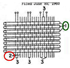 |
I found the evidence of this in a core rope memory patent; in this patent, the schematic as seen left, is shown and is described thus:
"When the magnetic easy axis of the magnetic thin-film wire 1 is in the circumferential direction thereof, the magnetic thin-film wires 1 are used as information lines (which function doubly as digit lines and sense lines), and the conductor wires 2 are used as word drive lines."
The wires 2, which are the wires which pass through or bypass the cores, are described as the drive lines, i.e. the wires which activate the cores. The magnetic thin-film wires 1, which are the wires I have indicated with an orange arrow are the sense lines.
The Univac core rope memory worked according to this principle, and this patent confirms my finding.
Furthermore, it is in an alternating current, rather than a continuous current which was sent into the drive lines (one at a time) – more efficient than using a continuous current (especially considering that the drive lines didn't have an important section). The electronic interface of the sense lines was turning the alternating current of the sense line into a continuous one.
The two Core Rope Memories – Univac on the right
So although the core rope memories of the two computers display some similarity, they work in a very different manner, the wires passing through or bypassing the cores being sense wires in the case of the Apollo memory – these wires being activation wires instead in the memory of Univac; in the case of the Univac memory, each core had an unique sense wire, so there was no problem regarding the division of current in the sense wires as with the memory of Apollo.
And that fact makes the whole difference between a core rope memory which can work, and one which cannot.
The Erasable Memory
Even the dynamic memory couldn't possibly work, because the 'write' current and the 'read' current were going through the same wire, which would have been impossible, since they must go through two separate wires.

The Incorrect Pulse Driver
In any event, the pulse driver circuit which was amplifying the 'read' impulse could not work because it has two blocked transistors. The computer's RAM memory itself was totally unworkable.

In short, this computer had no memory, none at all. Neither ROM nor RAM.
The CSM/LM computer's operating system had many major flaws:
-
The Apollo Guidance Computer used a technique of switchable memory which is absurd since it didn't use the full capability of the addressing system, and would lead to a waste of time and memory, both of which were very limited in the computer; and a switching executable program memory makes no sense, because it means that the instructions which follow the switching instruction would never be executed.
-
The computer did not have the minimal basic set of instructions of any normal processor, instead it had instructions that were impractical.
-
The computer did useless things which wasted processor time (like saving the contents of the instruction prioritised over saving its address – which is the only thing which should have been saved).
-
The computer provided instructions which computed something so weird in the accumulator (main register of a processor) that it was the equivalent of destroying its contents, and thus rendering the instructions unusable.
-
The computer had instructions that didn't require a parameter which would be necessary for these instructions to work properly.
-
The computer had other instructions which were unclear – they didn't specify what they were for.
-
The computer was said to be capable of real time (real time allows several tasks to run simultaneously) and yet it didn't even have the minimum environment necessary for real time operation (no stack, and no instruction to manage real time).
-
Although this system was already obsolete at the time of Apollo, the computer used the one-complement system (which makes a distinction between +0 and -0, and is less performant than the two-complement system).
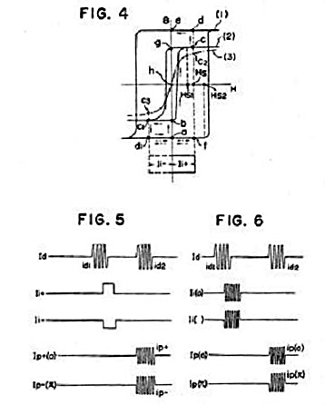
Incorrect Pulse IncrementThere were instructions for the computer to count hardware pulses.
Correct Pulse IncrementBut the hardware pulses should never have been counted with these instructions; they should have been counted by electronic counters that the processor could read at any moment with an I/O operation (and the I/O operation exists, it is described in the documentation). Counting hardware pulses with instructions of the processor would lead to a considerable waste of computer cycles.
Repetitive Task TestAnother absurdity is that the programmer had to insert repetitive tests into his program to check if another more important task had been scheduled, so that it could swap tasks if necessary. The documentation states that these tests had to be separated by less than ten milliseconds in the program – this is totally absurd, as this technique would lead to an enormous waste of computer cycles – either the priority task itself should have swapped the tasks, or eventually the less important task could have made the swap itself if it needed to protect a sequence of code (to update global variables for instance) that it would make at the end of this sequence.
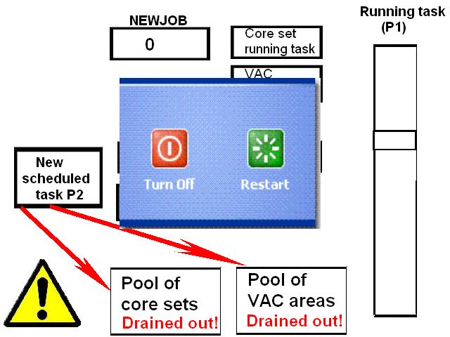
A Frozen AGC
A further absurdity is that resources were provided to a task which could not be run because more important tasks were running. The result could end in a number of waiting tasks which had allotted resources that a new, more important incoming task could not take, because these waiting tasks had drained all the available resources. In this case, the computer would be stuck (frozen), and would require rebooting.
An AGC Alarm
This is what was occurring when the famous alarm 1202 (as reported in the movie In the shadow of the Moon). In fact this alarm should never had happened. It only occurred due to the absurd way these tasks were managed.
The programs themselves were full of errors of syntax and logic. Some sequences of code simply did nothing.


DSKY Display Circuits
And, between the operator and the computer, there was the DSKY unit – a display coupled with a keypad/keyboard. One might have thought that this unit worked correctly. NO, not at all.
This schematic shows how the display worked:

The circuit circled in green shows the interface command of the relay line selection. The collectors of the transistors are connected through the relay coils and diodes to the collector of a transistor of which the base is connected to a word selection circuit. A relay's coil is activated when it is connected to a transistor activated by a line selection, and when the base of the transistor circled in pink is activated by the word selection it will then light a display segment.
The transistors circled in green (line selection) are obviously doubled for redundancy in case one of them would fail, and the diodes are supposed to isolate each one from the other; but these diodes are only useful in case one of them fails to open, not if it fails by being shorted. If it fails shorted, its diode will not prevent the 28 volts to be directly connected to the collector of the transistor (circled in pink) without taking into account the line selection from the computer, which means that the relay's coil to which it is connected will be activated, and will light a segment of the display without taking into account the line selection.
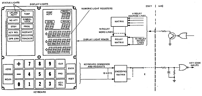
This schematic shows how the DSKY unit was connected:
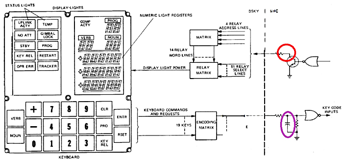
But there are several problems with this diagram.
Firstly, the collector of the transistor (circled in red) is not connected to a plus reference. So the relay matrix which follows would not be able to work correctly. And secondly, on the input of the NOR gate of the key code inputs there is a feed through capacitor – what is it doing there, you might wonder?
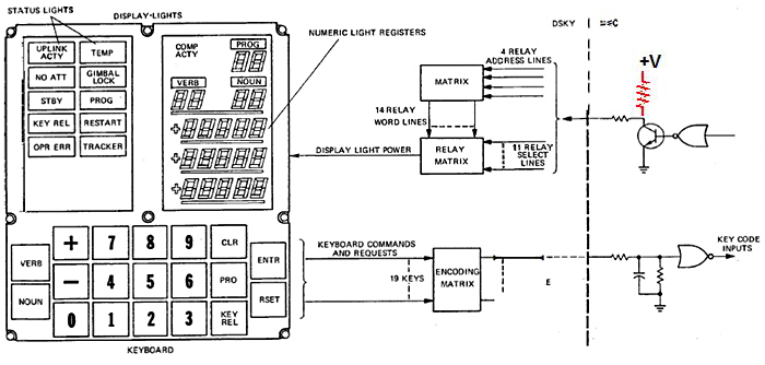
The DSKY Diagram Corrected
Here is an added connection to a plus reference on the transistor connected to the display light selection, which is necessary for the display light to work correctly.
Conclusion
With a DSKY unit which was not working correctly, the AGC definitely appears to be a complete fake.
But if this Apollo Guidance Computer was a joke it was because the engineers intended it to be so, and not because they were incompetent.
The engineers placed incoherence absolutely everywhere. All the electronic interfaces were stuffed with intentional errors.
Xavier Pascal
Aulis Online, 2012
Updated Xavier Pascal, October 2013
Note: Due to their size, the images in this article are not optimised for cell phones
Editor's Note: Sabotaging technological publications is still deployed today as a means of rendering defence technologies both ineffective and potentially expensive as well as time wasting should they fall (or be placed) into the wrong hands. It is certain that at the time of Apollo, any published computer data fell within the category of protecting the National Security of the United States. The question is, did this apply to the Apollo Space Project?
Thus some of the ‘impossibles’ found by Xavier Pascal might come under ‘protected information’. However, as Pascal argues, a strong case can also be made for whistle-blowing, with those tooting the whistle being fully aware that computer geeks were very thin on the ground in the 1960s. It may even be the case that this computer was not used at all. Whichever is the most likely scenario, this aspect of the Apollo investigation requires further study.
About the author
Xavier Pascal is a computer engineer specialising in real-time systems. He constructed a number of electronic interfaces with digital electronics in the nineteen seventies and eighties. He states that he is sufficiently qualified to read and to understand the technical documentation of the Apollo Guidance Computer, and his observations of the (intentional) flaws in the documents form the basis of his article.
![]()
This article is licensed under
a Creative Commons License
AULIS Online – Different Thinking