Lunar Module Descent and Landing:
Intentional Errors Introduced into the Record?
by Aerospace Engineer Xavier Pascal
Background
On July 20, Armstrong and Aldrin entered the LM again, made a final check, and at 100 hours, 12 minutes into the flight, the Eagle undocked and separated from Columbia for visual inspection. At 101 hours, 36 minutes, when the LM was behind the moon on its 13th orbit, the LM descent engine fired for 30 seconds to provide retrograde thrust and commence descent orbit insertion, changing to an orbit of 9 by 67 miles, on a trajectory that was virtually identical to that flown by Apollo 10. At 102 hours, 33 minutes, after Columbia and Eagle had reappeared from behind the moon and when the LM was about 300 miles uprange, powered descent initiation was performed with the descent engine firing for 756.3 seconds. After eight minutes, the LM was at "high gate" about 26,000 feet above the surface and about five miles from the landing site. The descent engine continued to provide braking thrust until about 102 hours, 45 minutes into the mission. Partially piloted manually by Armstrong, the Eagle landed in the Sea of Tranquility...
NASA History extract
Part One – The LM's Descent from the CSM
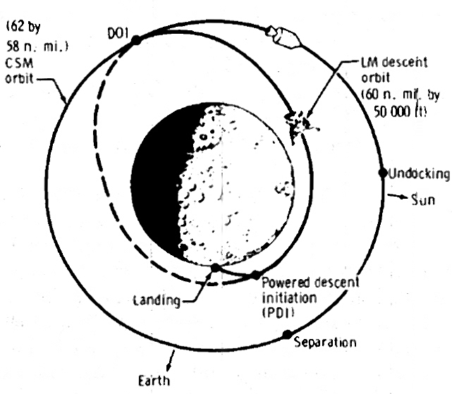 Figure 1 CSM/LM orbits |
The Apollo Experience Report, NASA Technical Note TN D-6846, is a mission planning document describing the descent and ascent of the lunar module (LM) on to and from the Moon. The above illustration is included in this document, and illustrates how the module commenced the descent orbit from which it started its powered descent to the lunar surface.
After separating from the command and service module (CSM) the LM didn't immediately start its powered descent from lunar orbit, as it was orbiting too far from the lunar surface. First, it had to achieve a lower orbital height. How did the LM reach this lower orbit? By following a natural orbit, rather than orbiting at a constant distance from the lunar surface, its distance from the lunar surface varied. Called a Hohmann transfer orbit, this is an elliptical orbit used to transfer between two circular orbits of different radii in the same plane. How did it insert itself into this orbit? It did so by altering its orbital speed so that it corresponded with the orbital speed of the transfer orbit at the contact point with the CSM's orbit.
The orbital speed of the CSM and the orbital speed of the transfer orbit can be computed using Kepler's law. According to the NASA Technical Note, the orbital speed of the transfer orbit was 75 feet/s less than the orbital speed of the CSM’s orbit at the contact point.
This means that the LM would have to reduce its orbital speed by 75 feet/s to place it into the transfer orbit. When the LM reached the closer orbit, there then had to be another manoeuvre to insert the LM into that closer orbit; one might think that since it was decreased at the start, this new manoeuvre would consist of increasing the orbital speed. But this is not so, because during its descent along the transfer orbit towards the lunar surface, the orbital speed of the LM had actually increased. Therefore, in order to achieve insertion when it reached the closer orbit, it had to decrease its orbital speed by that same value.
According to the document this speed decrease would be achieved in three steps:
1) A first manoeuvre throttling at 10% of the thrust for 15 seconds.
2) A second manoeuvre which consisted of throttling at 40% of the thrust over 13 seconds.
3) A third manoeuvre which consisted of an overburn making the LM lose 12 feet/s in 3 seconds.
Note that the document does not state at what percentage of the thrust the third manoeuvre corresponds to.
The knowledge of the maximum acceleration (or deceleration) of the engine allowed confirmation that this succession of manoeuvres effectively permitted the craft to obtain the desired reduction of speed of 75 feet/s.
Let us call this maximum acceleration Am.
1) The first manoeuvre caused a decrease in speed equal to Am x 0.1 x 15.
2) The second manoeuvre caused a decrease in speed equal to Am x 0.4 x 13.
Therefore the total decrease in speed would be equal to:
Am x (0.1 x 15 + 0.4 x 13)+12 = Am x 6.7 + 12
Is there any way of knowing the maximum acceleration of the engine, Am?
|

Yes, as NASA provides specifications of the LM:
– According to the record, the LM had a total mass equal to 15200kg, for the H-Series (the one of the first missions),
– And the LM's engine had a force of 43900 Newtons.
Therefore the LM's engine, with full tanks and maximal thrust, could deliver an acceleration of:
Am = 43900/15200 = 2.888 m/s² = 9.627 feet/s².
 Figure 3 LM descent |
We can now calculate the initial decrease in speed delivered by the engine's thrust:
Speed decrease = 9.627*6.7+12 = 76.5 feet/s.
You might say that it does not make much difference with the reduction of speed that must be applied, but a variation of one foot/s in the reduction of speed results in a variation of altitude of 1250 meters at the other end of the orbit, and this variation might cause the powered descent to fail.
The final over burn would make the LM lose 12 feet/s in 3 seconds; with the maximum thrust, the LM would lose 12 feet/s in: 12/9.627 = 1.246s.
This means that in the third manoeuvre to reduce the speed of 12 feet/s in 3 seconds, the LM applied a fraction of the thrust equal to 1.246/3 = 0.41, so that is 41%.
Remembering that the LM first throttled at 10%, then at 40% until it had obtained the desired reduction of speed. Now we can see that the third step used the same percentage of thrust as the second step.
However, this doesn’t make any sense. It started with a low throttle (10% thrust) and ended with a greater throttle (40% thrust). It should have been the converse – the LM should have started to throttle consistently, and thereafter more moderately at the end of the speed decrease, in order that it could adjust the speed decrease as precisely as possible.
So it appears to have been planned in reverse order. As already stated, a variation of a single foot/s at the start of the transfer orbit would cause a variation of altitude of 1250 m at the other end of the transfer orbit! By way of comparison, when parking a car, after your vehicle is almost parked, the car travels at a low speed to adjust your parking as accurately as possible. You don't do the converse, initially travel at a low speed, and when almost parked, manoeuvre at high speed to finish parking.
Why commence throttling at 10% instead of 40%? NASA states it is for the purpose of "center of gravity trimming", which means that the guidance would try to adjust the gimbaling system so that the thrust would be directed toward the center of gravity of the LM, otherwise there would be a misalignment torque, and this misalignment torque would make the LM turn.
 Figure 4 LM engine trimming |
Initially the gimbaling system was pre-adjusted so that the thrust was directed toward the center of gravity when the propellant tanks were full. As the propellant tanks empty during the descent, the center of gravity shifts, and so the guidance acts on the gimbaling system to reorient the thrust toward the new location of the center of gravity. And since the gimbaling system was supposed to have been pre-adjusted so that this trimming would not be necessary – there was no trimming to make.
 Figure 5 Saturn V launch |
The same principle applied to the Saturn V rocket when it lifted off. The gimbaling system was initially pre-adjusted so that the global thrust was aligned with the rocket's center of gravity when the tanks were full. As the rocket burned fuel, the gimbaling system was continuously adjusted so the thrust remained aligned with the center of gravity.
 Figure 6 Gimbaling system un-adjusted |
If the gimbaling system was not initially adjusted so that the thrust was aligned with the center of gravity, the guidance would not have the time to make this adjustment. It would be set off balance, and would crash before it had a chance to make this adjustment.
That's why it was totally incorrect when, in the movie In the Shadow of the Moon, astronauts Buzz Aldrin and Mike Collins said that as it lifted off they felt the rocket swaying because the gimbaling system was looking for the center of gravity. The fact that Buzz Aldrin and Mike Collins repeat this nonsense confirms that they were not in the Saturn V when it lifted off – if they had been on board they would not have felt this swaying movement they are talking about.
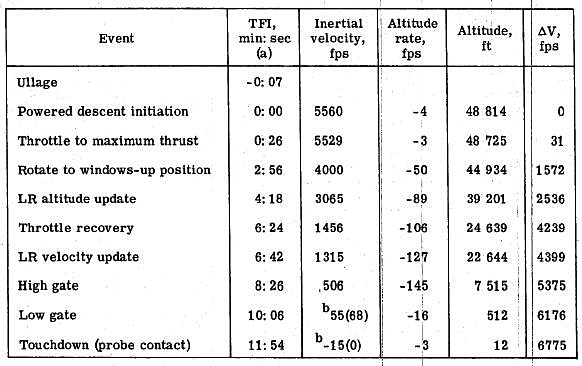 Figure 7 Powered descent summary chart |
The LM's descent – the above table (figure 7) contains many indications of fakery that will be explained.
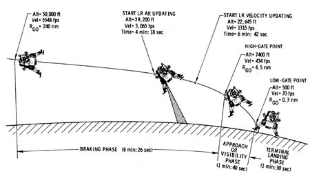 Figure 8 LM Braking phase |
The NASA text describes the operational phases of the lunar landing, starting with the braking phase which allowed the LM to lose most of its important horizontal velocity. The LM indeed had a very significant initial horizontal velocity relative to the Moon of almost 6000km/h that it had to lose before landing. Imagine what would happen if landing at such a velocity.
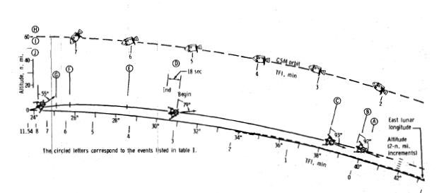 Figure 9 |
During the initial phase, the LM was oriented horizontally, because it had to use the thrust of its engine to both counter the horizontal velocity and decrease it. Initially, centrifugal force allowed it to counter the lunar attraction which means that it didn’t need to be countered. Progressively though, as the LM lost its horizontal velocity, the centrifugal force decreased, which means that the lunar attraction tended to increasingly attract the LM toward the Moon and increase the vertical speed. But, during the initial braking phase, the vertical velocity remained low relative to the horizontal velocity, and represented approximately only one hundredth of the horizontal velocity.
So, in this phase, the LM ignored the lunar attraction and concentrated the thrust of its engine to decrease the essential horizontal velocity, which means that the craft remained horizontal. After this phase, it started turning to a vertical orientation in order to start countering the lunar attraction before the vertical velocity became too high – moderately at first, then increasing as the horizontal velocity was reduced to end up in a full vertical mode.
This descent is far from being as trivial as some might imagine. The LM had to arrive near the lunar surface with both a moderate vertical and horizontal speed. If the LM arrived near the surface with too great a vertical speed, it would surely crash onto the lunar surface, there would be no way that it could recover from such a situation.
On the other hand, if the LM arrived near the surface with too high a horizontal speed, it would also be doomed, there is no way that it could have recovered from such a situation either. Figure 9 above demonstrates that the LM's descent required very precise control – no error could be tolerated during the descent.
The table below (Figure 10) contains the following columns:
– The Event column describes the current Event.
– The TFI column indicates the time elapsed between the start of the powered descent and the current event.
– The Inertial velocity column represents the horizontal speed of the LM, and is indicated in feet per second; this velocity starts from the orbital speed of the module.
– The Altitude rate column is the rate of the altitude decrease, and represents the vertical speed of the module; it starts from 0 at the parking orbit, and initially increases; when the module starts fighting the lunar attraction, it then decreases; it is also indicated in feet per second.
– The Altitude column represents the altitude of the LM, that is its distance to the lunar surface, expressed in feet.
– The last command Delta V (the triangle before the 'V' is the greek symbol Delta – generally used to indicate a difference) representing the difference between the speed that the LM would have if no thrust had been applied, and the current actual speed of the LM; it represents the thrust, for it is the thrust that enables it to obtain this difference.
 Figure 10 Radar velocity |
According to the NASA Technical document the velocity could only be acquired by the doppler radar from the altitude of 22,000 feet. This means that the doppler radar only allowed the acquisition of the velocities colored in green; the velocities in red could not be acquired by the radar. However, this is completely absurd, because doppler radar is not used from a given altitude, it is used as soon as the signal comes back, and it is precisely the doppler radar that allowed the LM to acquire these speeds.
 Figure 11 Radar altitude |
Moreover, with regard to the altitude radar, NASA states that it was only taken into account from an altitude of 39,000 feet. This means that the radar could only acquire the altitudes which have been colored green, and not those colored red. But once again this is absurd, for it is precisely the altitude radar which would allows it to obtain the altitude. In reality the altitude radar can only be used when the signal comes back, and not from any given altitude.
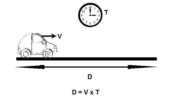 Figure 12 |
In order to check the next figure, some explanations are needed. When a vehicle travels at a constant speed V for a distance D, and during a time T, we have the relationship: D = V xT.
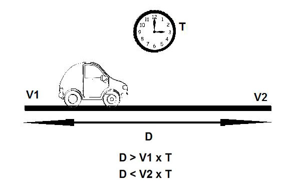 Figure 13 |
Therefore, when a vehicle starts traveling the distance D at a speed V1, and continually accelerates, and is at a speed V2 at the end of that distance, and traveled during a time T, we have the relationships:
D > V1 x T
and
D < V2 x T
If one of these relationships is not respected, there is an anomaly.
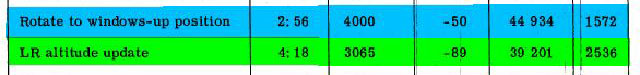 Figure 14 |
Between the events colored blue (rotate to windows-up position) and green (LR altitude update), there is a difference of time equal to 4:18-2:56 = 82 seconds; at the first of these two events (rotate to windows-up position), the altitude rate is indicated as -50; at the second of these two events (LR altitude update), the altitude rate is indicated as -89; that means that the altitude rate was between 50 and 89 feet per second between these two events.
 |
So to sum up: the minimal loss of altitude is 4100 feet, and the maximal loss of altitude is 7298 feet; now the difference of altitude between these two events is 5733 feet; as 5733 is between the minimum (4100) and the maximum (7298) computed from the rate, there is a coherence here.
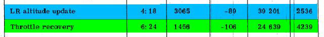 Figure 16 |
Between the two events colored blue (LR altitude update) and green (throttle recovery), there is a difference of time equal to 6:24-4:18 = 126 seconds; at the first of these two events (LR altitude update), the altitude rate is indicated as -89; at the second of these two events, the altitude rate is indicated as -106; that means that the altitude rate is comprised between 89 and 106 feet per second between these two events.
 |
Summing up these data: the minimal loss of altitude is 11,214 feet, and the maximal loss of altitude is 13,356 feet; now the difference of altitude between these two events is 14,562 feet. that is 1,206 feet greater than the maximum loss of altitude given by the altitude rate. We now have an obvious incoherence, a situation which is totally impossible, and another clue that this table does not show a normal descent.
Figure 7 (repeated) Powered descent summary chart |
Now we are going to consider the powered descent and the Delta V column of the above chart. The Delta V represents the difference between the speed that the LM would have if no thrust had been applied, and the actual speed, it represents the thrust.
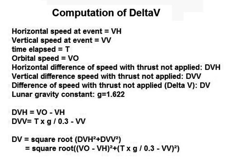 |
In order to be able to check whether the Delta V indicated in the last column is normal, we have to know how to compute it. The Delta V is a combination of a horizontal Delta V, and a vertical Delta V. If no thrust was applied, the module would keep its orbital speed. So the horizontal Delta V is the difference between the orbital speed and the current horizontal speed.
Concerning the vertical speed, if no thrust was applied, the module would have an acceleration equal to the lunar gravity constant ( g = 1.622), which means that after an interval of time T, the vertical speed would be equal to the gravity constant multiplied by the time T; there is a division by 0.3 to convert this speed into feet per second. The current vertical speed is subtracted from this computed value to obtain the vertical Delta V. Then the Delta V is computed as the square root of the sum of the squares of the horizontal Delta V and the vertical Delta V, according to the Pythagoras theorem.
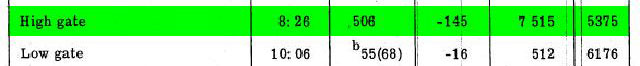 Figure 19 |
Now we know how to compute the Delta V, we are going to compute it at the High gate event.
– The current horizontal speed is 506 feet/s.
– The current indicated time is 8:26 = 506 s, and the current vertical speed (altitude rate) is 145 feet/s.
 |
– The horizontal Delta V is equal to: Delta VH = 5560-506 = 5054 feet/s.
– The vertical Delta V is equal to: Delta VV = 1.622*506/0.3-145 = 2590 feet/s.
It is now possible to calculate the Delta V: Delta V = SquareRoot (DeltaVH²+DeltaVV²) = SquareRoot (5054²+2590²) = 5679 feet/s.
But in the table of the powered descent, the current Delta V is indicated as only 5375 feet/s. That makes a difference of more than 300 feet/s. This means that the thrust which had been applied by the LM's engine was not sufficient to obtain the speeds indicated in the table at this event. There must therefore be a mysterious 'hidden force' which helped the LM to reduce its speed.
 Figure 21 |
Let's now look at the Low gate event:
– The current horizontal speed is 68 feet/s (the number between brackets, the other is relative to the lunar surface),
– The current indicated time is 10:26 = 626 s, and the current vertical speed (Altitude rate) is 16 feet/s.
 |
– The horizontal Delta V is equal to: Delta VH = 5560-68 = 5492 feet/s.
– The vertical Delta V is equal to: Delta VV = 1.622*626/0.3-16 = 3368 feet/s.
Now we can calculate the Delta V: Delta V=SquareRoot(DeltaVH²+DeltaVV²) = SquareRoot (5492²+3368²) = 6442 feet/s. But the current Delta V is indicated as only 6176 feet/s. That makes a difference of 266 feet/s. It is less than the previous difference, but at more than 200 feet/s, it is still relatively important.
Once again the thrust that has been applied by the LM's engine was not sufficient to obtain the speeds indicated in the table at this event. So, once again, there must be a mysterious 'hidden force' which helped the LM to reduce this speed.
Next let's take the last event, Touchdown:
– The current horizontal speed is 0 feet/s (the number between brackets).
– The current indicated time is 11:54 = 714 s, and the current vertical speed (Altitude rate) is 3 feet/s.
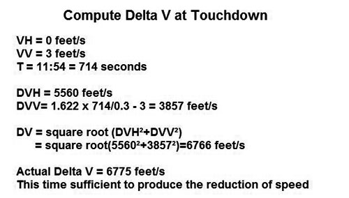 |
– So the horizontal Delta V is equal to: Delta VH = 5560 feet/s.
– The vertical Delta V is equal to: Delta VV = 1.622*714/0.3-3 = 3857 feet/s.
We can calculate the Delta V: Delta V = SquareRoot (DeltaVH²+DeltaVV²) = SquareRoot (5560²+3857²) = 6766 feet/s. But this time (instead of being consistently smaller by several hundred feet/s as in the previous events) the indicated Delta V is only slightly greater than the theoretical Delta V. Therefore this time, the thrust was sufficient to obtain the indicated speeds.
So what happened? How is it that the final Delta V could be so close to the final theoretical Delta V when the previous values of the Delta V were consistently smaller than the theoretical Delta V? The answer lies in that NASA technical note (TN D-6846), which states:
In addition, 85 fps is added to assure 2 minutes of flying time in the landing phase.
Also, a 60-fps AV is added for LPD operation in the approach phase to avoid large craters (1000 to 2000 feet in diameter) in the landing area.
This is quite surprising, as the guidance makes precise calculations, and does not make such suppositions. It does not artificially increase the calculated thrust just in case there might be unexpected craters. This must be misdirection, and a further indication that the descent table makes no sense at all.
 Figure 25 Orbit of the Moon around Earth |
Some explanations regarding the last indication of a problem. As the Moon orbits the Earth counter-clockwise, it also slowly spins counter-clockwise, so from Earth the Moon always shows the same side, as in the above simplified animation.
 Figure 23 (repeated) |
The last indicated horizontal speed corresponds precisely with the displacement speed of the lunar surface. It is indicated negatively, as the LM landed in a direction in opposition to the rotation of the Moon.
 Figure 26 LM synchronised with the lunar surface |
If the indicated speed was absolute, as with the previous speeds, it would mean that the lunar surface and the LM would move synchronously with each other, and so it would mean that the LM was stationary relative to the lunar surface. Moreover, the LM must be absolutely stationary to the lunar surface when it landed. Otherwise if it moved laterally, it would surely tip over when coming into contact with the lunar surface.
 |
And now the final piece of information. The above annotation states that the last horizontal speed (along with the previous one) is no more absolute than the previous speeds of the table were, but the speed is now relative to the lunar surface!
 Figure 28 LM's lateral speed relative to the lunar surface |
Conclusion to Part One
Rather than moving synchronously relative to the lunar surface, as it would have done if the indicated speed had been absolute, the LM had a lateral speed relative to the lunar surface, which was equal to the displacement speed of the lunar surface.
This speed may not seem particularly significant, at 15 feet per second, that is 16 km/h. But the LM was 13.1232ft (4 meters) above the lunar surface, and it descended at a speed of 3.2808ft/s (1 m/s). This means that it would touch the surface in 4 seconds, and it would not have had the time during those 4 seconds to null this speed with its lateral thrusters (which were far less powerful than the main engine).
Therefore the inevitable conclusion must be that potentially, the LM would have tipped over when coming into contact with the lunar surface.
• • • •
Part Two – Stopping the Engine and Landing the Lunar Module
 Figure 1 LM landing pad probes |
The LM had collapsible surface contact probes attached to the undersides of the LM's landing pads. The function of these probes was to detect the lunar surface before the footpads touched the surface. (As another Apollo researcher has pointed out, the LM according to the record came in at an angle, and those contact probes dragged along the lunar surface, therefore what happened to the drag marks left by the surface contact probes?)
On landing, the skirt of the descent engine was very close to the lunar surface. It would have been dangerous for the descent engine to be firing when the LM touched down; that's why the descent engine had to be shut off immediately before actually landing.
 Figure 2 Close up of contact probe |
The LM Operations Handbook states that the probe lengths were 5' 7.2" (1.7 meters). The descent table indicates that when the LM was close to the Moon, it was descending at a speed of 1 m/s. This means that when these probes detected the surface, there remained less than 1.7 seconds to shut off the descent engine. In reality there remained even less than that, as the descent engine should be shut off before the module was too close to the lunar surface, so the descent engine had to be shut down after no more than one second once the probes detected the landing surface – when the footpads were at 1.7 meters from touchdown.
 Figure 3 Landing probe contact |
When at least one of the probes had touched the lunar surface a lamp warned the astronaut(s) to immediately shut off the descent engine. This was to be achieved by pressing a stop button so that when the module touched down, the descent engine was already off.
 Figure 4 Detection interface circuit |
Figure 4 is a schematic of the detection interface for the footpad probes. When a probe detected the surface, this interface warning lamp lit up to instruct an astronaut to press the stop button, thereby shutting off the engine.
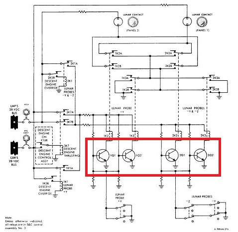 Figure 5 Transistor assembly |
The interface (figure 5) contained four transistors. Why four transistors? This assembly of transistors was mounted in a redundant way which guaranteed that whichever of the transistors failed or shorted:
- The lamp would not be lit before one of the probes touched the lunar surface,
- The lamp would light up when at least one of the probes touched the surface.
Meaning that the astronauts would be warned in a timely fashion of the proximity of the lunar surface – never prematurely.
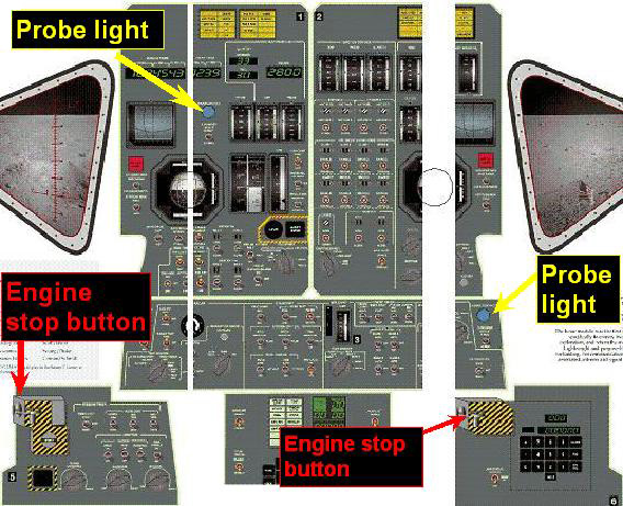 Figure 6 Probe warning lights and stop buttons |
 |
Therefore, when the astronauts saw the probe warning light up (indicated with a yellow arrow, figure 6), they were supposed to press a stop button (indicated with a red arrow); there were two of them, one for each astronaut (probably because if one astronaut encountered a difficulty, the other could still take care of shutting off the engine).
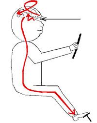
The problem is that between the moment the astronaut responsible for shutting off the engine saw the warning light, and the moment that he effectively pressed the stop button, there would be a reaction time. Furthermore, when the astronaut pressed the engine stop button, a spring returned the button to its rest position after being released (figure 8).
To make the point, between the moment that a car driver sees an obstacle and the moment that the driver presses the brake pedal, there is a reaction time. Although of course, this reaction time depends on the reflexes of the individual concerned – for a car driver this is usually estimated as being one second.
 Figure 8 Engine stop animation |
The engine stop button had to be pressed in order to shut down the descent engine. When the astronaut pressed the button, a spring returned the button to its rest position after being released.
Figure 9 below is the descent engine stop button circuit diagram. You can see that when the button was not pressed, the contact was closed; but when it was pressed, the contact opened. When the stop button was released, the contact was closed again on reaching its rest position. The closed contact then sent a pulse that energised a coil, shutting off the descent engine.
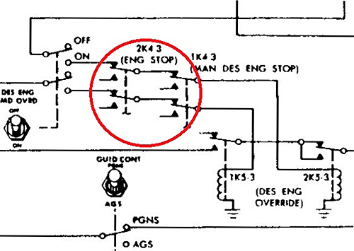 Figure 9 Engine stop circuit |
Therefore when an astronaut pressed the button, nothing happened. Only after the astronaut released the button would it return to its rest position, closing the contact again, thereby allowing the engine to shut off.
 Figure 10 Engine stop circuit diagram |
The animation in figure 10 shows what happens when the astronaut presses and releases the stop button. But imagine in the heat of such an intense moment, an astronaut presses the button, but inadvertently delays releasing it. If that were to happen, the descent engine would not be shut down.
 Figure 11 Electromechanical relays |
The big question is, could all this have been made more effective, efficient and reliable? Yes, absolutely it could. Indeed, the detection interface of the probes contained electromechanical relays, framed in red in figure 11.
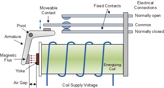 Figure 12 Relay |
An electromechanical relay (figure 12) is a switch that can be activated, not by an operator, but automatically by a current which could be sent to a coil; the coil would then attract a switch by induction.
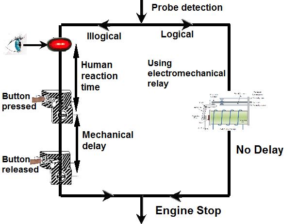 Figure 13 Electromechanical relay circuit |
Such an electromechanical relay could perfectly well have been used to instantly shut off the descent engine – it would have been far more efficient than requiring the astronauts to watch for a warning light. There would have been no delay, it would have been very precise – the engine would have stopped precisely on time.
Conclusion to Part Two
This part of the investigation has revealed a very strange procedure chosen by the engineers. To summarise, between the moment that the warning light came on and when the engine was effectively stopped, there was a delay which could have exceeded the maximum time allowed for shutting off the descent engine. There was a procedure that instead could have been selected – an electromechanical relay automatically shutting off the engine – neat and precise. The engine would have been shut down automatically at the exact moment.
 Figure 15 Decent engine skirt |
Why was it so important that the descent engine was shut down before the module touched the lunar surface? In this close-up part of the Apollo 11 LM (AS11-50-5864), it is clear that the skirt of the descent engine was very near to the lunar surface; if the descent engine was still firing, it would have severely damaged the structure of the LM.
 |
The conclusion therefore is that the engineers apparently conceived a procedure for a lunar landing that had every potential of ending catastrophically.
But what do any of these findings matter if the Apollo missions never ever actually landed on the Moon?
• • • •
Part Three – Correct Attitude of the CSM in Lunar Orbit?
Introduction
In still photographs and DAC 16mm film clips, the CSM is seen with its nose up as it orbits the Moon along with the LM. This is particularly the case with Apollo 11, and in film footage of Apollo 15. (This is the case even after the LM had separated from the CSM, while it continued to orbit close to the CSM for around half an orbit). It is normal for the CSM to be seen with a vertical attitude, because when a satellite orbits a planet, it adopts an attitude such that its geometric center and its center of mass are vertically aligned, with its center of gravity under or beneath its geometric center (i.e. closer to the planet).
It is obvious that the nozzle skirt extension of the service module is lighter than the rest of the CSM, which would place the center of mass above the geometric center when the CSM is vertical. Consequently, with the craft's center of mass located beneath the geometric center when the CSM is depicted orbiting the Moon, the CSM should not be oriented with its nose up, but rather with the nose down, and the nozzle skirt uppermost.
By orienting the CSM the 'wrong way round' when depicted orbiting the Moon, it would appear that the engineers intentionally left a strong indication of an intentional error, for they could hardly be unaware of how the CSM should really appear when orbiting the Moon.
We might tend to think that a CSM should orbit the Moon horizontal to the lunar surface, because this is the way craft are generally depicted when orbiting a planet in illustrations/movie animations as in figures 1 and 1a, as well as by NASA in its own documents. But let’s investigate this question further.

Figure 1
 Figure 1a Figure 1a |
Is the fact that the CSM is depicted orbiting in a vertical mode with it nose uppermost hinting at a false representation? Or should the CSM really be orbiting the Moon in a horizontal attitude as shown in figures 1 and 1a above?
Figure 2
If the lunar attraction was constant, and only the centrifugal force was variable (because the part of the craft closer to the Moon had a greater angular speed than the part farther from it), the difference of centrifugal forces would make the CSM adopt a horizontal attitude when it starts from an attitude in bias.

Figure 3
But the lunar attraction also varies with the distance to the Moon, and it varies even more than the centrifugal force, as it varies with the inverse of the square of the distance to the Moon's center, while the the centrifugal force only varies with the inverse of this distance (that's why, the closer to the lunar surface, the greater the orbital speed is necessary to remain in orbit).
Consequently, when the CSM is in bias, the lower part is subject to a gravitational force which is a little greater than the centrifugal force, while the upper part has a gravitational force which is conversely slightly smaller than the centrifugal force, and this tends to make the CSM take a vertical attitude instead. Therefore, if the attitude of the CSM is not controlled, it naturally tends to become vertical, so that the center of mass of the craft and its geometric center become vertically aligned. Moreover, the center of mass is under the geometric center.

Figure 4
This photograph (figure 4, AS11-37-5445) was taken during the Apollo 11 mission. It shows the CSM orbiting the Moon, with the lunar surface below the craft, viewed from the LM which was located above it. After the LM had separated from the CSM, it didn't immediately start its descent to the lunar surface, but initially orbited the Moon close to the CSM for some time. However, the CSM is not oriented horizontally as one might expect, but instead it is depicted in a vertical position but with the nose of the CSM uppermost.
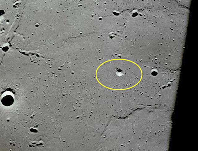
Figure 5
The photo in figure 5 (AS11-37-5447), also taken during Apollo 11, two frames after the previous image, shows a more distant CSM.
There is also some 16mm DAC footage of the CSM taken from the LM where the CSM is orbiting the Moon with a vertical attitude, again with its nose uppermost. In this footage, the lunar surface passes rapidly at times, and at other times more slowly. Therefore, based on the filming rate being constant, it means that the CSM changed its orbital speed, which is totally impossible. The orbital speed is determined by the planet's gravity and the distance of the craft to the planet's surface, so it's speed cannot vary, otherwise the craft would leave its orbit.
But are these the only hints of errors offered in this imagery and the DAC 16mm film footage?
Figure 6
Our own satellite, the Moon, has an almost constant attitude relative to Earth (which varies a little with the Moon's libration) as in figure 7 below:

Figure 7
If the Moon always shows us the same side and never reveals its hidden side, it is because the side we see is a little heavier than the hidden far side. This means that its center of mass doesn't exactly coincide with its geometric center, and is therefore closer to Earth.

Figure 8
Though it's becoming rare with recent technological developments, some small satellites don't have the benefit of an attitude control, and use the gravity gradient to orient them relative to Earth. The natural attitude corresponding to the repartition of the mass of the satellite varies somewhat, but it remains good enough for the use of uncontrolled small satellites.
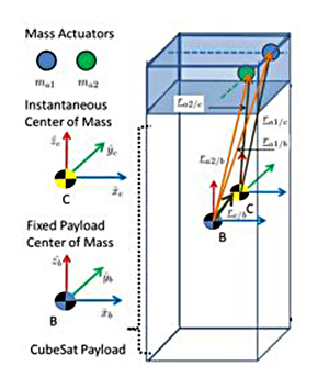
Figure 9
Some small satellites are able to correct their attitude by adjusting their repartition of mass (by moving a weight located inside them).
Figure 10
Other small satellites also use magnetic attitude control.

Figure 11
Such satellites use the Earth's magnetic field. But, unlike mass attitude control, which would also work for a satellite orbiting the Moon, the magnetic attitude control doesn't work for a satellite orbiting the Moon, because the Moon has no magnetic field.

Figure 12
Larger satellites need to have an attitude controlled rather better than one utilising the natural repartition of mass. The latter doesn't hold the desired attitude precisely. Furthermore, it varies more than the precision desired for the satellite. In the case of a satellite requiring maintenance of its attitude it needs to be continuously corrected in order for it to hold the desired attitude as accurately as possible.
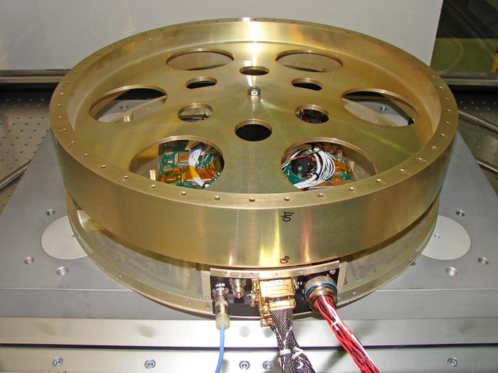
Figure 13 Reaction wheel
Such a satellite uses a piece of technology that can operate continually as it uses very little energy. This device is a reaction wheel (figure 13) – or a momentum wheel that is even more precise), that can control and turn the satellite with great precision.
Figure 14
To supply the energy needed to control the reaction wheel, the satellite uses solar energy.

Figure 15
Figure 15 illustrates how the loop of the attitude control works. The current angles and accelerations of the satellite are read by gyroscopes and accelerometers and from these measurements, and the current position of the satellite, the satellite's onboard computer updates the satellite's current attitude. This attitude is then compared with the desired attitude. Then from the comparative difference, commands are implemented to make the reaction wheels of the satellite correct the satellite's attitude to bring it closer to the desired attitude...and so forth.
You may ask how the gyroscopes are initialised, as there is no astronaut aboard to make a star alignment.

Figure 16
Initialisation of the gyroscopes is fairly simple: A signal is emitted from Earth, and the satellite is turned in both directions until the reception of this signal is optimal. The corresponding position is then used to initialise the zero setting of the gyroscopes.
Figure 17
Now that we have established that it would be normal for the CSM to adopt a vertical attitude when orbiting the Moon, the question is to consider whether it should orbit with its nose uppermost as in figure 17 above.
Figure 18
... Or with its nose pointing downwards as in figure 18.
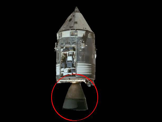
Figure 19
It is obvious that the nozzle skirt extension of the CSM's engine must be lighter than the rest of the CSM.

Figure 20
This fact would place the CSM's center of mass above its geometric center when it is oriented up. But we have seen that the center of mass must be under or below the geometric center when the module orbits the Moon.

Figure 21
This means that the CSM would be oriented down when it orbits the Moon, so that its center of mass is under its geometric center, as demonstrated in figure 21.
Figure 22
Conclusion to Part Three
The command module should have orbited the Moon as oriented in figure 22 above.
Not as in the Apollo imagery – as in figure 23:
Figure 23
Consequently, the Apollo images should have the nozzle skirt extension of the CSM's engine uppermost – and not its nose cone uppermost. And on the DAC 16mm footage filmed from the LM with the CSM orbiting the Moon, the CSM should have been oriented vertically. BUT with its nose down rather than with its nose up.
The inevitable conclusion therefore is that the orientation of the craft in these Apollo images is incorrect – but intentional. In so doing the engineers and image creators have purposely left a very strong indication of fakery – a rather loud blow on that whistle.
Xavier Pascal
Aulis Online, April 2018
Note: Due to their large size photographs in this article are not optimised for viewing on cell phones
![]()
This article is licensed under
a Creative Commons License
Comment on this investigation by an Apollo researcher with insider knowledge and experience of the space industry
Monsieur Pascal's conclusions are correct as far as I can determine without spending a great deal of time analyzing the work. Some of the documents that Xavier Pascal is critiquing are not ‘After Action’ analytical reports but rather, they are theoretical position papers of an experimental mission that could not be observed. They represent what the original planners assumed would happen in a perfect world or on a good day. Often such papers are not thoroughly ‘vetted’ as it were. So long as they appeared correct, the execution of the thrusting maneuvers’ (if actually performed) would end up VFR (visual flight rules).
In this case however, since the goal of the mission was to ‘prove’ to ‘everyone’ that the mission was successful, after-action critiquing of the actual mission execution would serve no purpose and in fact be counterproductive. Furthermore; I don’t believe that anyone at NASA ever considered that there would be ‘domestic’ challenges to the accuracy of the reports. In order to bolster mission successes other ‘empirical’ evidence was provided, albeit the source of that evidence remains in doubt.
The bulk of material evidence provided ‘after each mission’ was ‘so called’ photographic records, recordings of radio transmissions and some rock samples (moon rocks?). Literally nothing related to the Apollo missions was ‘corrected’ after the missions. Spokespeople for NASA, when pressured, would offer some curt response to critics but no comprehensive explanation of glaring anomalies was ever offered other than satirical retorts and excuses provided by sycophants.
Xavier Pascal is an aerospace engineer and a very experienced IT computer professional specialising in real-time systems. Over the years he has constructed a number of electronic interfaces with digital electronics. Xavier Pascal is sufficiently qualified to read and understand the technical documentation of the technology deployed in the Apollo space project, and his observations of the intentional flaws in the documents form much of the basis of this article.
AULIS Online – Different Thinking