Images taken at Eye Level, not chest height
Ray Tracing of Apollo 16 images reveals an
inconsistency between the photos and videos
Luis E. Bilbao, PhD
Introduction
Astronauts took still photographs during the Apollo missions with a Hasselblad camera mounted on a support at chest height, as shown in Fig. 1. These cameras did not have a viewfinder, and were not held at eye level. In fact, the astronauts were trained to take photographs with the camera mounted on a chest bracket. This mounting relied on moving the body to align the required field of view, and left both hands free for non-photographic tasks. The camera's focus and shutter speed controls were adjusted manually, while the winding to advance from one frame to the next was done with an electric motor drive. It took approximately 1.6 seconds from the moment a photograph was taken until the film was in position for the next shot. So this was the least amount of time that could separate the taking of two consecutive photographs.
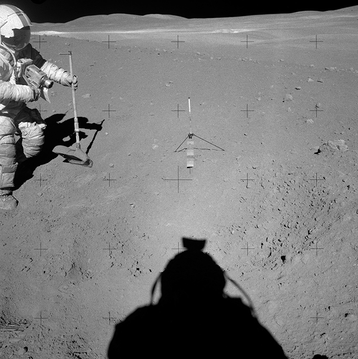 Fig. 1: Apollo 16, photo AS16-110-18019, showing the mounting of the Hasselblad camera at the astronaut's chest height. |
There are many photographs where the photographer's shadow can be seen, as in Fig. 1. As shown in the Appendix, based on the various objects present in the photographs and their respective shadows, it is possible to determine the projections of the light rays onto the photographic plane. In real 3D space, the daylight rays are parallel because the only light source is the Sun, but their projections on the plane of the photograph may converge at a point. Since the rays are straight lines, we will use the concept of their extension to infinity in both directions, that is, we will refer to those straight lines as rays.
If the Sun is in the semi-space in front of the camera, the projection of the rays will converge towards the image of the Sun. On the other hand, if it is in the semi-space behind the camera, the convergence will be towards a point located in the plane of the photographic film, which will be called the point of convergence. It will be within the shadow projected by the camera, as discussed in more detail in the next section. They will only appear parallel when the Sun is neither in front nor behind the camera, meaning the source is in the plane of the photograph.
It is important to note that the point of convergence on the film is separated from the horizon by an angle equal to the elevation of the Sun, but in the opposite direction, meaning it is below the horizon at the same angular distance as the Sun. This means that the point of convergence would be the point where the image of a light source located diametrically opposite to the Sun would form.
In this paper, by tracing the projections of the rays, the point of convergence in the photograph and its relative position with respect to other observed objects will be determined – and particularly in relation to the astronaut's shadow when it is present. As shown in the Appendix, the point of convergence would correspond to the shadow produced by an imaginary point located at the front principal point of the camera's lens. Since this imaginary point is inside the body of the lens, the point of convergence should be located within the shadow of the lens, whether that shadow is visible or not, or whether it is within the shadow of another object, such as the astronaut's body.
Ray Tracing Method
In this next section, the ray tracing method that will be used in the subsequent analysis of the sequence of the Apollo 16 photographs numbered AS16-113-18349 through to AS16-113-18370 is described. This is done to compare it with the video footage from the rover's camera that purports to show the Apollo 16 astronaut while taking that sequence.
Let's consider a simple example of well-defined objects, such as in the photograph in Fig. 2, taken with a cellphone camera. Although the shadows of the parallel crossbars are also parallel on the ground, their 2D projection appears as converging shadows (towards a vanishing point). The same situation on uneven terrain can result in photographs with distorted shadows, meaning the shadows may not appear straight. For this reason, care must be taken when analysing the shadows of objects, as the terrain's effect can make them seem abnormal. In contrast, light rays are always straight, both in real 3D space and in the photograph, except for, of course, distortions inherent to the camera itself.
 Fig. 2. Photograph taken with a cellphone camera, where three points and their corresponding shadows have been marked (labelled as 1-1, 2-2, and 3-3). These are used to determine the direction of the rays. |
Although the rays are not visible in either real space or the photograph, there is a simple way to trace them. This is done by drawing a straight line, connecting a point on an object with its respective shadow. In Fig. 2, three-point/shadow pairs are shown, and when they are connected, the rays are drawn, as illustrated in Fig. 3.
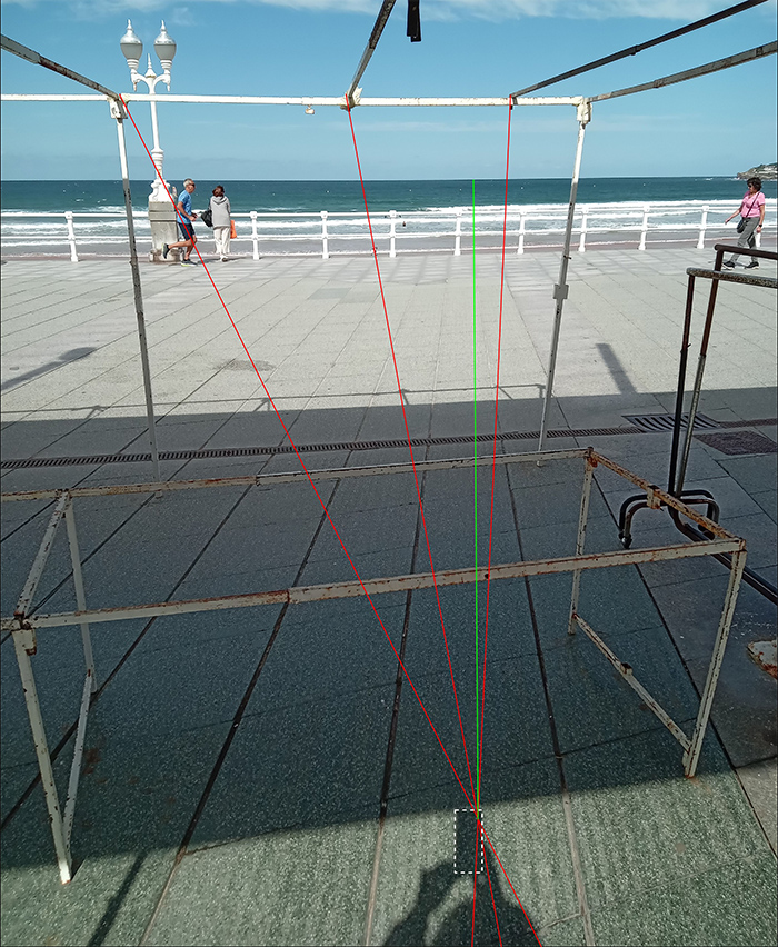 Fig. 3. Ray tracing based on the points defined in the photograph of Fig. 2, with the camera held above the photographer's eye level. The dashed white box outlines the shadow of the phone. It can be observed that the point of convergence is within the phone's shadow, in the area of the camera. A green line indicates the distance to the horizon. |
As expected, the point of convergence lies within the shadow of the phone. More precisely, in the area where the camera is located on the phone. (Near the top-right corner when viewed from the front). A green straight line indicates the distance to the horizon. The angular distance measured is 44.6º, which approximately matches the Sun's elevation angle at the time of the photograph, which was 44.3º. In this case, knowing the horizon line allows the Sun's elevation angle to be found with relative precision, and conversely, knowing the Sun's elevation angle allows the horizon line to be determined, as we will do in the case of the Apollo 16 photographs.
It is important to note that, as seen from the camera, the point of convergence (which corresponds to the shadow of the front principal point) forms an angle of the same magnitude, but in the opposite direction to the angle the Sun makes with the horizon. In other words, if the Sun is at an angle a above the horizon, the point of convergence will be at an angle a below the horizon.
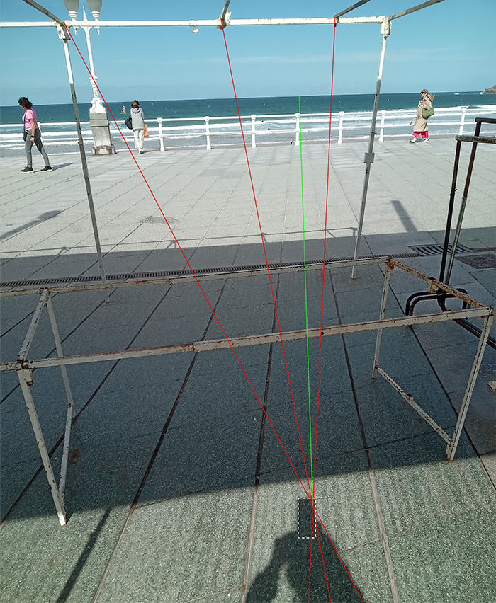 Fig. 4. Ray tracing determines the point of convergence with the camera positioned at the photographer's eye level. A white dashed box outlines the contour of the phone's shadow. It can be seen that the point of convergence falls within the phone's shadow in the camera area. The green line indicates the distance to the horizon. |
Using the same procedure, the points of convergence are obtained for the photograph in Fig. 4, with the camera now held at the eye level of the photographer, and in Fig. 5, with the camera positioned at the chest level of the photographer. Note that in Fig. 5, because the Sun is relatively high and the camera is held about 30cm away from the photographer relative to the photographer's shadow, the camera's shadow appears to be higher than its actual position.
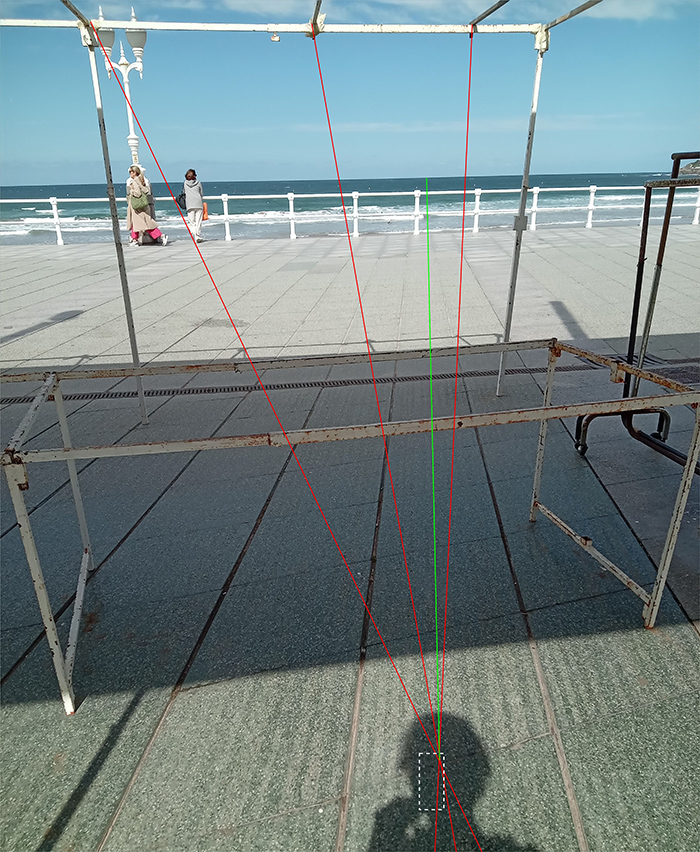 Fig. 5. Another example of determining the point of convergence, in this case with the camera positioned at the photographer's chest level. A white dashed box outlines the contour of the phone's shadow. The point of convergence is seen within the phone's shadow, which falls within the photographer's shadow. The green line indicates the distance to the horizon. |
Without conducting a detailed study of measurement errors, it can be said that these examples show that the uncertainty of this method, using basic equipment and without particular precautions, is not higher than 1°. It is worth clarifying that, while in these instances the orientation of the camera's optical axis is not relevant, these 'cellphone' photographs are cropped from a larger original; therefore, the optical axis does not coincide with the centre of the shown image.
Furthermore, the camera used in these examples is smaller than the photographer's Hasselblad which means that practical distinctions cannot be made between the various locations, such as the camera body, the lens, or the principal planes. The error margin in locating the point of convergence is actually larger than the camera's dimensions. In contrast, the camera used in the Apollo missions is considerably larger, with dimensions comparable to surrounding objects, such as the astronaut's helmet or backpack.
Below is a Hasselblad EL Data Camera with a Biogon f/5.6-60 mm lens, whose characteristics can be found at a Zeiss historical products web page.1
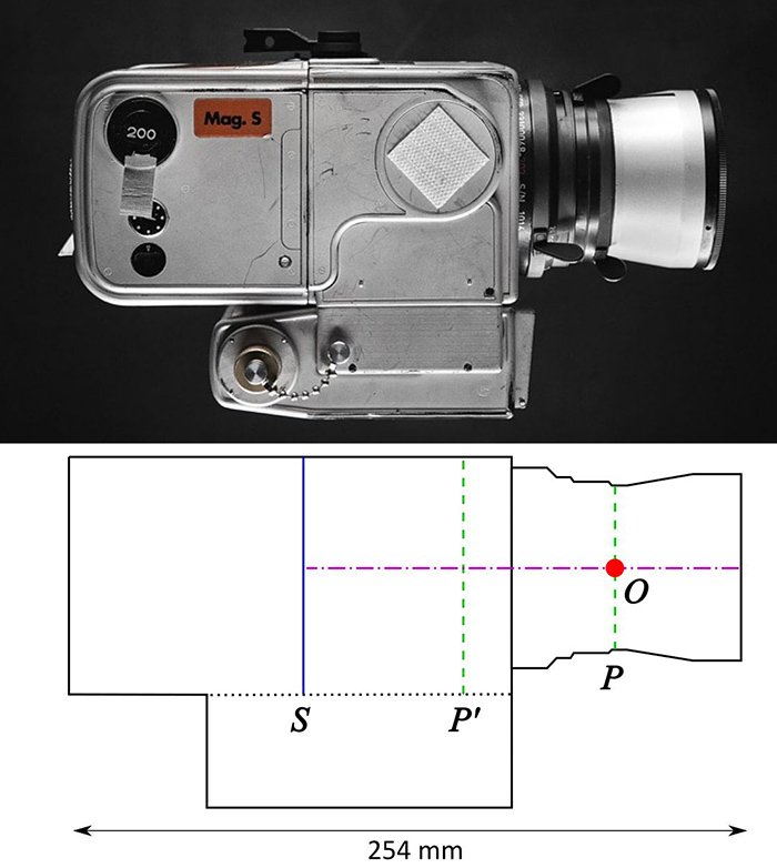 |
Figure 6. Upper: Hasselblad camera with a Biogon f/5.6 60mm lens similar to the camera assigned to the Apollo missions. Lower: Diagram of the various planes and axes described in the text below.
In Fig. 6, a camera similar to the one used in the Apollo missions is shown alongside a schematic of its main optical features. The horizontal magenta dashed line indicates the optical axis. The solid vertical blue line marks the position of the film plane, the vertical green dashed lines locate the principal planes: the front principal plane marked with a P and the rear principal plane marked P'. The intersection of the front principal plane with the camera's optical axis determines the front principal point, here marked with a red circle at O. The position of this point is important because, as shown in the Appendix, ray convergence on the film will occur at the point corresponding to the shadow of this cardinal point.
As mentioned above, the camera is positioned at the astronaut’s chest level, so when the astronaut has their back to the sun, their body’s shadow conceals the camera’s shadow, as shown in Fig. 7. In this figure, photographs are used as a reference to illustrate the typical dimensions of the PLSS backpack, helmet, camera, and shadow. It can be observed that depending on the angle formed by the incident ray with respect to the camera’s optical axis, different situations can arise as the angle increases: (a) for small angles the camera’s shadow will remain within the shadow of the backpack; (b) there will be one angle at which it aligns with the upper edge of the backpack; (c) then it will fall within the helmet’s shadow; (d) up to a limit angle where it aligns with the top of the helmet.
For larger angles, the rays are no longer obstructed by the astronaut’s body, so the camera’s shadow would be visible, but this is not shown here, as the Sun’s elevation was never that high during the time of the Apollo missions. The position of the point of convergence relative to the astronaut’s shadow is also shown for these four cases.
|

|
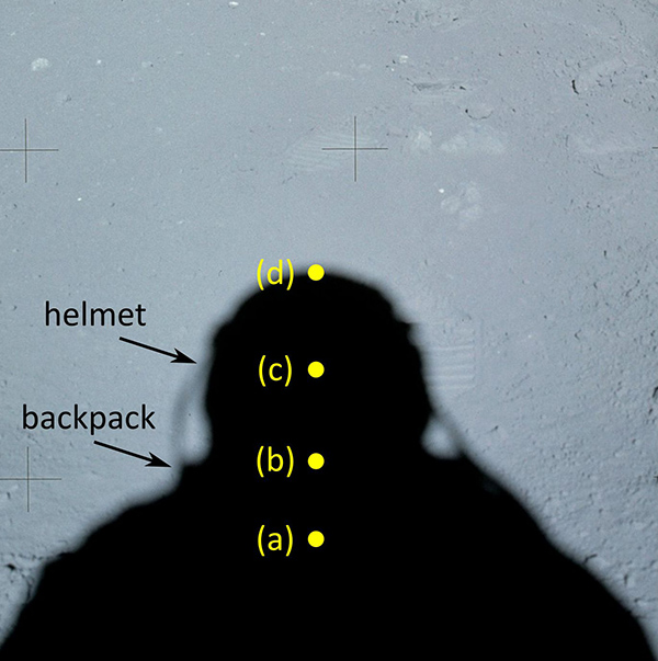
Also note that Fig. 7b is used solely to illustrate the relative positions of the shadows of the backpack, the helmet, and the camera's front principal point. The position of the point of convergence relative to the astronaut's shadow is also shown for these four cases. Characteristic values of these angles, α, are as follows: (a) α ≲ 20º, (b) α ≲ 20º, (c) 20º ≲ α ≲ 45º, and (d) α ≈ 45º.
It is important to note that the relevant angle is the one between the ray and the optical axis, as the backpack, helmet, and camera can be considered as a single, rigid unit – there is no relative movement between them. In fact, when the astronaut takes a photograph downward, they must lean forward, and when taking a horizontal photograph, they need to lean back, as seen in the video referenced in the next section. This implies a coordinated movement between the astronaut's body angle relative to the vertical and the angle between the optical axis and the horizontal.2
In summary, ray tracing allows us to locate the point of convergence, from which the Sun's elevation angle can be determined if the horizon is known (which differs very little from a horizontal plane), or the horizon can be found if the Sun's elevation angle is known. Additionally, in the case of the astronaut and the chest-mounted Hasselblad camera, it provides information about the angle between the direction of the rays and the camera's optical axis based on the location of the point of convergence relative to the astronaut's shadow.
Sequence of photos and simultaneous video
Among the numerous photographs from Apollo 16 there is a panoramic sequence in which the photographer captures images while rotating 360 degrees. This sequence comprises photographs AS16-113-18349 through AS16-113-18370, which can be downloaded from NASA's official site on the Apollo 16 Image Library page.3
In total, there are 22 photos, and according to the description accompanying the photograph index, it is known that the eleventh photo in the sequence AS16-113-18359 was taken at 122:13:49 (referring to hh:mm:ss from the mission start time [GET]. Knowing the time allows the determination of the Sun's altitude at that moment, which was 23.6º above the horizon.
Although the exact times of the other photographs are unknown, given that the total time to take them is much shorter than the duration of a lunar day, the Sun's position can be considered fixed throughout this event. There are three photographs within this sequence in which the photographer astronaut's shadow appears, allowing the point of convergence position to be determined using the ray tracing method.
Simultaneously, there is a video taken from the rover camera that shows the astronaut during almost the entire sequence. This is video a16v.1221123, which can be downloaded from the Apollo 16 Video Library page.4 In this video, the first photo in the sequence (AS16-113-18349) is taken approximately 1m 41s after the video begins.
Photograph AS16-113-18349
For ray tracing, a point on an object is selected as the origin, and the line passing through this point and its corresponding shadow is traced, as shown in Fig. 8 for photograph AS16-113-18349.
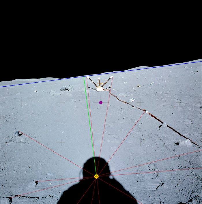
Fig. 8: Ray tracing for photograph AS16-113-18349. Using certain points and their corresponding shadows, rays are traced with red lines, intersecting within the region marked by the yellow circle. Additionally, with a green line of 23.6º in angular length and a possible vertical orientation, the horizon line (blue line) is determined. The magenta point at the center of the photograph indicates the optical axis.
Unlike the simplified case seen in Fig. 3, here the rays do not intersect at a single point; rather, they converge within a relatively small area, marked by a yellow circle in the figure with a diameter of approximately 1º. This could be due to various factors, including the possibility that a shadow is obscured by an irregularity, causing a misplacement of the corresponding point, or that the point and its shadow are too close together, making the ray extrapolation highly uncertain.
There is also the possibility of more than one light source, as observed in the Apollo 11 and Apollo 14 missions. Thus, tracing multiple rays is useful for statistical consistency. In any case, it is evident that the actual intersection lies within an area indicated by the yellow circle, that is, within the astronaut's helmet shadow.
Additionally, knowing that the horizon should be 23.6º above the point of convergence, a green line with an angular length of 23.6° was drawn from this point, in a possible vertical direction, so that its upper end marks the blue horizon line. In this case, it coincides with the visible horizon in the photograph's background.
Finally, the camera's optical axis – marked by the centre of the largest cross located at the centre of the photograph and indicated by a magenta circle – lies below the horizon, in this case by 6.8º. If so, the angle between the camera's optical axis and the sunlight rays would be 16.8º, which, as shown in Fig. 7a, corresponds to a small-angle case, meaning the point of convergence should be within the backpack's shadow and not within the helmet's shadow, as shown in this figure.
Another way to view this contradiction is by noting that the position of the point of convergence within the helmet's shadow, slightly above the backpack's shadow, implies an angle of just over 20º between the ray and the optical axis. This suggests that the photograph would have been taken in a horizontal (or nearly horizontal) orientation, which contradicts the observed difference between the horizon and the optical axis.
Photograph AS16-113-18350
The next photograph, AS16-113-18350, also allows the position of the point of convergence to be determined through ray tracing, as shown in Fig. 9.
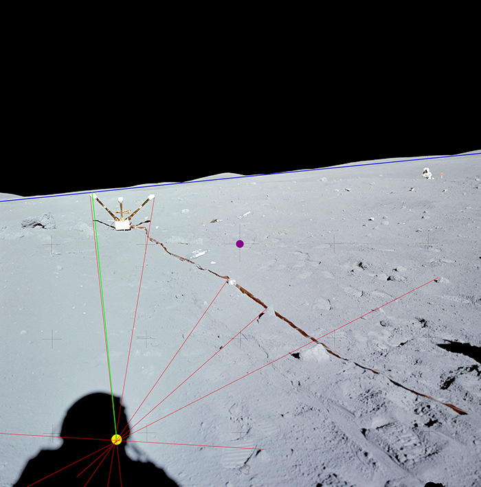 |
Fig. 9. Ray tracing for photograph AS16-113-18350.
The rays, represented by red lines, intersect within a relatively small region, marked by a yellow circle, located in the helmet shadow area. From this region, the green line is drawn in the possible vertical direction with an angular length of 23.6º to determine the blue horizon line.
The analysis of this photograph leads to a similar result; on one hand, the point of convergence is located at the lower part of the helmet's shadow, and on the other hand, the angle between the horizon and the camera's axis – 6.5º in this case – results in an angle between the sunlight and the optical axis of only 17.1º. Therefore, according to the data in Fig. 7, the point of convergence should be within the shadow of the backpack.
Photograph AS16-113-18370
The final photograph in the panoramic series, AS16-113-18370, also shows the shadow of the photographing astronaut, see Fig. 10.
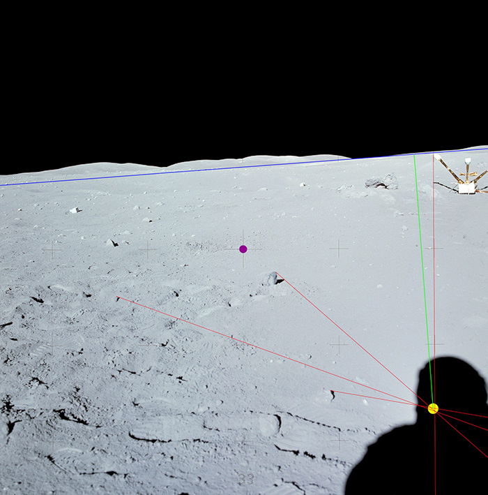 |
Figure 10. Ray tracing for photograph AS16-113-18370.
Following the guidelines from previous analyses, it is once again observed that the rays (red lines) intersect in an area (yellow circle) within the shadow of the astronaut's helmet, indicating that this region contains the point of convergence.
In a vertical direction, 23.6º upward (green line), a possible horizon is found, as indicated by the blue line. The optical axis, marked by a magenta circle, is 7.8º from the horizon and 15.8º from the direction of the rays. Under these conditions, the point of convergence should be within the shadow of the backpack, not the helmet.
These three photographs consistently reveal the same features. The point of convergence appears within the helmet's shadow from which a reasonably accurate horizon line can be drawn that coincides with the landscape background. Since the optical axis passes through the centre of the photograph (marked by a larger cross), its angle with the horizon can be determined. Given the Sun's elevation, the angle between the rays and the optical axis can also be calculated. When comparing this angle with a typical configuration of the astronaut with a backpack, helmet, and camera, it proves to be too small for the point of convergence to appear within the helmet's shadow, as seen in the photo.
Video a16v.1221123
In one section of the video a16v.1221123, the sequence of the astronaut taking the photographs that form the panorama mentioned above is shown. It was captured by the camera located on the rover, which was about 30 meters away from the astronaut.
The video analysis is carried out by studying the photographer's movements frame by frame as he takes the photographs. The video contains 5,831 colour frames with a resolution of 352x240, with a duration of just over 3 minutes and 14 seconds. The first thing that stands out is that in every group of 5 frames, 1 is repeated, meaning there are 4 distinct frames and the fifth is a repetition of the fourth.
The sequence of interest begins around frame 2410, when the astronaut positions himself to take the panorama photographs. Note that the astronaut's body is slightly tilted forward because the backpack shifts the centre of mass backward, necessitating a forward lean to maintain balance. Additionally, in this position, the camera's optical axis is angled downward by approximately 17º.
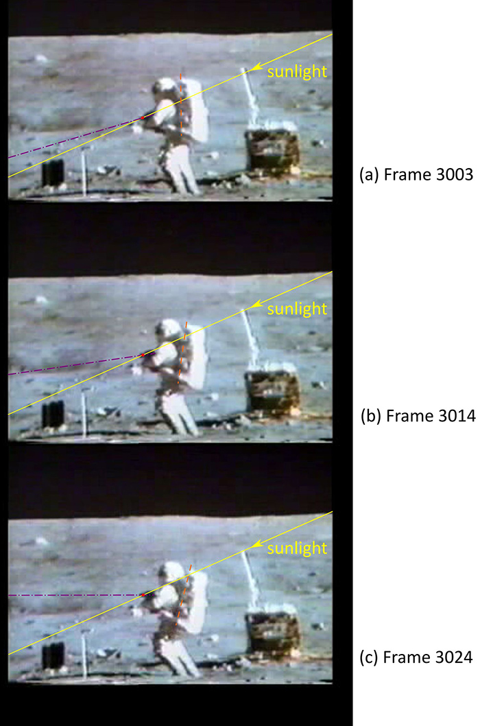
Fig. 11 : Three frames from the sequence show the astronaut raising the camera's axis to start photographing.
(a) Frame 3003: initial position, with the camera's axis pointing approximately 17º downward (magenta dashed line);
(b) Frame 3014: with knees bent and leaning back, the axis is now around 7.5º downward;
(c) Frame 3024: the axis is nearly horizontal, and it is likely that photograph AS16-113-18349 was taken in this position. The ray (yellow line) passing through the front principal point (red dot) is also shown, along with the orange dashed line indicating the backpack's rotation, moving in sync with the camera's axis.
Before starting the photo sequence, the astronaut remains in this position for about twenty seconds. From frame 3003, he begins raising the camera's optical axis by bending his knees and leaning backward, as shown in Fig. 11. In frame 3024, the camera reaches a horizontal axis, marking the beginning of the photography session. An intermediate position, frame 3014, is also shown, where the optical axis is tilted approximately 7.5º downward. Note that the backpack also rotates by a similar angle as the camera's axis, supporting the hypothesis that the astronaut's body, helmet, backpack, and camera move together in unison.
Taking into account the Sun's angle of incidence and the location of the front principal point, it can be seen in Fig. 11 that for both a 17º and a 7.5º downward tilt of the optical axis, the point of convergence should fall within the shadow of the backpack and not within the helmet's shadow. Only when the camera is in a horizontal position does the point of convergence appear at the lower part of the helmet's shadow, just above the backpack's shadow.
The manoeuvre formed by the astronaut to align the camera horizontally is not something that only occurs in the first frames of the sequence. As shown in Fig. 12, this manoeuvre is repeated as the astronaut turns and continues photographing.
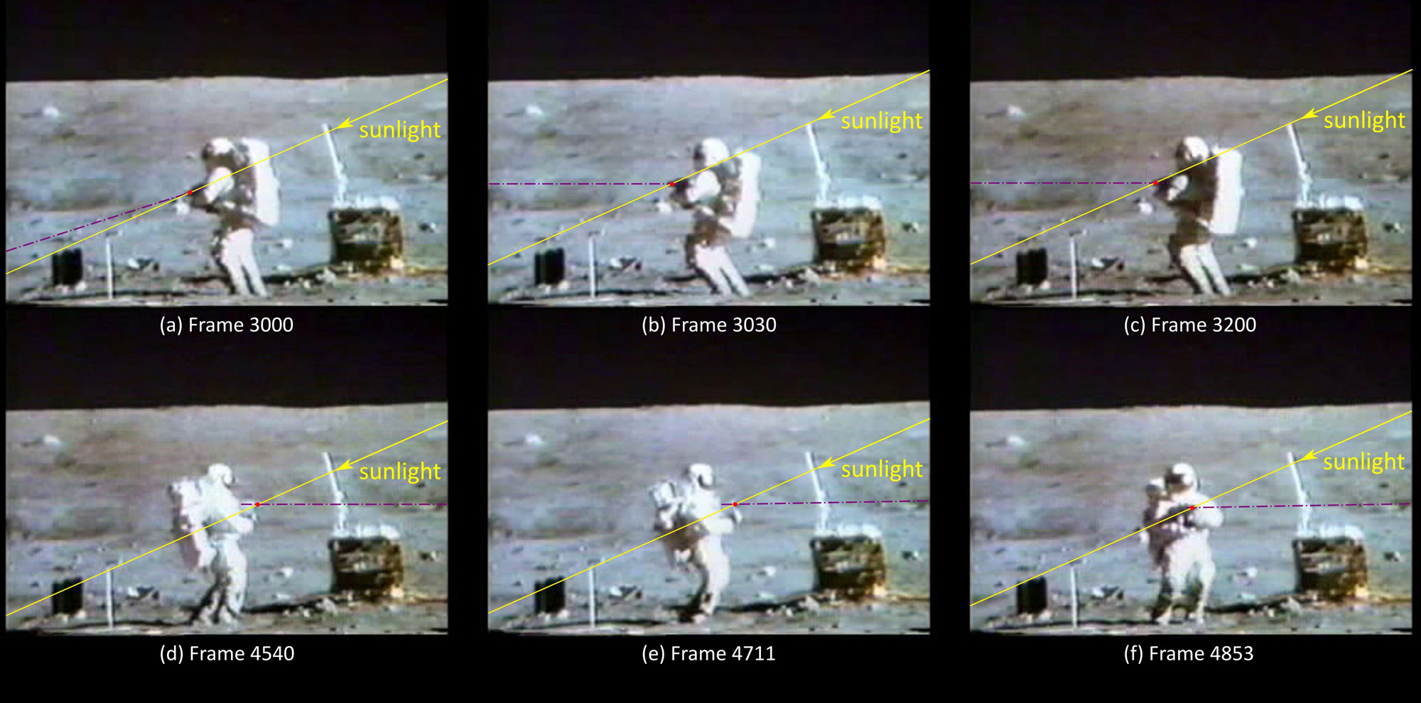 |
Figure 12. Click to enlarge. Some frames from the video sequence a16v.1221123 show the astronaut taking photographs AS16-113-18349 to AS16-113-18370. The movement to align the camera's axis horizontally is clearly visible.
This analysis indicates that the intent behind taking all the photographs is to orient the camera with its horizontal axis. On the other hand, when considering the horizon found in the three photographs in which the astronaut's shadow is visible, it is possible to trace the horizon across all the photographs that make up the panorama, since there is a composition incorporating all images from the panorama covering 360. (See a16pan360_18349-70emj)5
Although the photographs may not be perfectly aligned, extending the horizon based on the three previously mentioned photographs provides an idea of its location in the remaining images. In all cases it is observed that the centre of the photograph – that is, the camera's optical axis – is always below the horizon, with an angle that varies between 3° and 11°, despite the fact that in the video they appear to have been taken horizontally. Although the angular orientation cannot be determined precisely in the video frames, for the cases analysed, a difference of 7° can be clearly distinguished compared to an almost horizontal orientation, as seen in Fig. 11c.
Summary
From the analysis of the photographic sequence AS16-113-18349 to AS16-113-18370 and the video a16v.1221123, it is concluded that there is an inconsistency in the orientation of the photographic camera's axis.
To summarize, the following points are observed:
- Point of Convergence in Photographs: From ray tracing in photographs AS16-113-18349, AS16-113-18350, and AS16-113-18370, the point of convergence is located within the shadow cast by the lower part of the helmet, just above the backpack's shadow. This is shown by the yellow circle in Figs. 8,9,10.
- Determination of the Horizon: Knowing the Sun's height, the horizon can be established from the point of convergence, which aligns well with the visual horizon at the background of each photograph, as indicated by the blue line in Figs. 8,9,10.
- Optical Axis Below Horizon: Since the centre of the photographs also marks the intersection of the optical axis (depicted by the magenta circle in Figs. 8,9,10), the angular distance between this centre and the horizon can be measured. In all three cases, it is observed that the optical axis is approximately 7° below the horizon.
- Horizontal Orientation in Video: In contrast, the video shows that the photographs were taken with the camera axis oriented nearly horizontally, as seen in several frames in Fig. 12. Additionally, if the photographs had been taken at a 7° downward angle relative to the horizon, the shadow of the front principal point would appear within the shadow of the backpack, as depicted in Fig. 11(b) and schematized in Fig. 7(a), rather than within the helmet's shadow, as observed in the photographs.
- Necessary Orientation for Convergence in Helmet's Shadow: The only way for the point of convergence to fall within the helmet's shadow is if the optical axis forms an angle greater than 20° with the solar rays, which implies that the camera is oriented almost horizontally (see Fig.11(c), similar to the diagram in Fig.7(b)). If this were the case, however, the centre of the photograph should align with the horizon line, yet this is not the case in any of the photographs.
In brief, the evidence that the camera is oriented with its axis in a horizontal position arises from the fact that the point of convergence is within the helmet's shadow and from the camera's orientation visible in the video frames. Meanwhile, the evidence that it is oriented approximately 7° downward comes from the distance between the centre of the photograph and the horizon, which was determined based on the point of convergence and the Sun's height.
Conclusions
1. An important consideration is that all previous analysis assumes the Sun as the sole source of illumination. However, in the case of artificial light sources, light rays may not be parallel in 3D space, leading to one or more points of convergence based on the characteristics and relative position of these sources with respect to the objects of interest. Consequently, the relationship between the image of this real convergence of rays and the camera's shadow will be more complex than in the case of parallel rays.
Specifically, the shadow image of the front principal point will appear separated from the image of this actual convergence occurring in 3D space, with the distance determined by the properties of the light source, the geometry of the objects, and the camera itself. Therefore, a plausible explanation for any inconsistency regarding the camera orientation could be that the scene is illuminated by non-parallel artificial light.
2. The inconsistencies present in each of the three photographs – specifically, the location of the convergence point within the helmet's shadow (suggesting a horizontal camera axis) and the distance from the optical axis to the horizon (implying a downward tilt of the camera axis) – could, for instance, be explained if the camera were not rigidly attached to the astronaut's body. If the camera could move or rotate independently of the astronaut's movements, rather than being fixed to a chest mount, it might have been positioned at a greater height. In any case, the discrepancy between the photographs and the video can only be fully understood if we consider that they were taken at different times and under different conditions.
According to NASA, there was no other camera available to take the still photographs. There was no possibility that the Hassleblad camera was deployed at eye level to take these and other lunar surface photos during the claimed Apollo missions on the Moon. Moreover, the video coverage clearly shows the camera fitted to the chest mount.
Therefore, the only way for these images to have been taken from eye level is if they were taken elsewhere, in a studio environment. This means that – contrary to what is claimed by NASA – at least one of these photographs is not what the agency claims it to be. More likely, none of the still images correspond to a true and accurate photographic record of astronauts on the Moon.
Luis E. Bilbao
Aulis Online, December 2024
About the Author
Luis Ernesto Bilbao has a PhD in Physics from the University of Buenos Aires, is Adjunct Professor, and Independent Researcher, INFIP CONICET, UBA (the Faculty of Exact and Natural Sciences, University of Buenos Aires, Argentina).
The Institute of Plasma Physics (INFIP), dependent on the CONICET and the FCEyN-UBA, is a center carrying out pure and applied research in a wide variety of subjects of this discipline. The INFIP researchers have extensive knowledge and many years of experience in this branch of physics, with the publication of more than 600 works since 1983.
Editor’s Note
This significant finding by Luis E Bilbao confirms Professor David Groves' analysis of the camera height in AS11-40-5903 that indicates the famous photograph of Aldrin taken during Apollo 11 photograph was taken from eye level and not from the chest height (see Dark Moon Appendix, p536). The photographer that is reflected in the visor is neither standing on an object/rock to give him extra height, nor is he holding the camera at eye level.
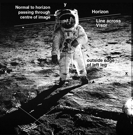
AS11-40-5903
Professor David Groves determined that, "the reflection in the visor (with the camera at chest height) is not that of the photographer of the main image".
Also by Luis E. Bilbao, PhD:
Apollo 11: A Second Light Source in the Famous Photograph?
Apollo 14: Second Light Source Confirmed
Apollo: The LM Double Shadow Question
References
1. Zeiss Biogon Lens page visited September 30, 2024.
2. Not all astronauts and their spacesuits are exactly alike, so the angular values mentioned above should be regarded as approximate. Also note that (while not applicable to the Apollo missions) technically, for high Sun elevations and therefore larger angles, the rays are no longer obstructed by the astronaut's body, so the camera's shadow would be visible. But this is not shown here, as the Sun's elevation was never that high during the Apollo missions.
3. NASA Apollo 16 Image Library visited September 15, 2024.
4. NASA Apollo 16 Video Library visited September 15, 2024.
5. NASA Apollo 16 Uploads visited October 10, 2024.
Appendix
![]() Images taken at Eye Level Appendix PDF
Images taken at Eye Level Appendix PDF
![]()
This article is licensed under
a Creative Commons License
AULIS Online – Different Thinking